ABSTRACT


MAIN

  • 1. Introduction

  • 2.Three dimensional numerical model

  • 3.Analysis of results

  • 4. Conclusions

1. Introduction

Maintaining the stability of the tunnel face during excavation is an important engineering design problem in difficult grounds since in these geotechnical conditions failure at the face can progress quickly and cause the complete tunnel collapse or an unacceptable land subsidence when the work is carried out at shallow depth.

The application of tunnel reinforcing techniques, such as jet grouting arch, steel pipe umbrella and precutting in advance, can reduce the problem of stability in radial direction, but longitudinal movements are still difficult to control if the section

is large and/or the ground is particularly poor.

It has recently been introduced in tunnelling practice the use of reinforced fiberglass pipes or bars into the core to be excavated as a preventive support layout. This technique, initially developed jointly with the mechanical precut in clay, has been widely applied to other geotechnical conditions as the only type of reinforcement or joined with other ground pre-consolidation and/or reinforcement techniques (e.g. steel pipes or jet-grouting umbrella).

Therefore it can be said that the knowledge of the behavior of the mass portion, ahead the tunnel face, in ground with poor geotechnical characteristics, constitutes an indispensable premise for a correct 

design of the supports, of the possible reinfor-cement of the ground to be excavated, of the best sequence of operative stages, of the admissible distance from the face and the supports and of the excavation section (full face or staged excavation).

On the other hand it is necessary to know, if reinforcement with fiberglass is to be used the stability improvement effect which is obtained.

Table 1. Geotechnical properties adopted in the carried out models

Model a

Model b

ground behavior

Elasto-ideally plastic

Elasto-plastic with strain softening

Yield function

Mohr-Coulomb with an associate flow rule

Mohr-Coulomb with an associate flow rule

(residual strength for σp > 0.004)

density

1900 kg/m3

1900 kg/m3

peak cohesion:

0.2 MPa

0.2 MPa

residual cohesion:

-

0.1 MPa

peak friction angle

18°

18° 

residual friction angle

-

elastic bulk modulus

150 MPa

150 MPa

elastic shear modulus

80 MPa

80 Mpa

Since the stress and displacement condition ahead the tunnel face is three-dimensional the study can be done only using numerical models. In this work the effect of a systematic tunnel face bolting has been studied using a three-dimensional FLAC code by comparing different geometry of reinforcement layout and different geomechanical ground properties. The approach has allowed to put in evidence the improvement on the stability conditions also with the comparison of some measurements carried out in the real tunnel taken as example.

http://static.apub.kr/journalsite/sites/kta/2004-006-03/N0550060307/images/PIC421C.gif

Fig. 1 Schematic trend (out of scale) of the adopted

strain softening behavior for both friction

angle and cohesion

2.Three dimensional numerical model

The problem of face stability conditions and the effect of longitudinal face reinforcement has been studied in this work by means of numerical model analyses especially carried out using a three- dimensional Finite Difference code (FLAC-3D)  (ITASCA, 1993).

The set-up model (100 m high; 100 m wide; and 100 m long) is based on the geometry and geo-technical parameters found in a tunnel in Italy where face reinforcing has been widely used. On this basis a systematic parametric analysis has been performed allowing a very good general overview of the behavior of the tunnel face reinforcement.

The numerical model geometry is that of a circular tunnel of 12 m diameter with 100 m overburden (undisturbed stress condition hydrostatic with http://static.apub.kr/journalsite/sites/kta/2004-006-03/N0550060307/images/PIC475D.gifv =http://static.apub.kr/journalsite/sites/kta/2004-006-03/N0550060307/images/PIC476E.gifo =1.9 MPa) while the geotechnical parameters are those of the Variegated Clay formation (Argille Varicolori) obtained with laboratory tests but two different ground behavior have been analysed (this choice was taken to verify the influence of the adopted ground behavior on the numerical analysis results). The geotechnical properties adopted in the analyses are given in Table 1.

http://static.apub.kr/journalsite/sites/kta/2004-006-03/N0550060307/images/PIC478E.gif

FLAC3D 2.00

Settings: Model Perspective

16:21:37 Tue Jun 22 1999

http://static.apub.kr/journalsite/sites/kta/2004-006-03/N0550060307/images/PIC47AE.gif

Center:     Rotation:

X: 5.000e+001  X:  0.000

Y: 5.000e+001  X:  0.000

Z: 5.000e+001  X: 30.000

Dist: 3.265e+002 Mag:    1

        Ang: 22.500

Surface

POLITECNICO DITORINO

Dip.di. Georisorse e Territorio

Fig. 2 Scheme of the numerical model and detail of

the FLAC 3D model

http://static.apub.kr/journalsite/sites/kta/2004-006-03/N0550060307/images/PIC47EE.gif

Fig. 3 Plastic zone ahead the tunnel face along

the tunnel axis for the carried out analyses

The excavation method foresees full face advancement in the ground that has preventively been reinforced with a fiber glass pipes layout. The tunnel support is obtained by modeling the shotcrete, installed at the same step of the excavation and the final lining installed a step after (that is to say that in the reference section (located in the middle of the model) the final lining is installed at a distance of 1m from the tunnel face).

The modeled pipes behavior is described by an elastic law and the sliding parameters are chosen to prevent any sliding between the bolts and the rock mass.

Fig. 2 shows the model dimensions, boundary conditions and the mesh scheme. The scheme of the modeled excavation and support phases and model types are given in Table 2 and 3.

3.Analysis of results

The extension of the plastic zones for the various analysis ahead the tunnel face, measured along the axis of the tunnel is described in fig. 3. It is possible to note that the results without pipes of the numerical model and of those of the simpler convergence-confinement approach are in good agreement.

It can also remarked the great influence on the results of the adopted rock mass mechanical behavior that is bigger for a reduced number of pipes on the face. The choice of an elasto-ideally plastic model therefore can lead to wrong results if the rock mass behavior is strain softenig. For obtaining displacements values of the same entity of the strain softening model the cohesion of the ideally plastic model must be 10 times lower.

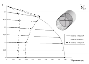
The displacements at the tunnel face are given in fig. 4 and 5. It can be observed from fig. 5 that the strain softening models give quite good results if compared with the real site measurements. The general trend of the measured and computed values show a global behavior with a well defined elbow which represent the point after which the face reinforcing cannot control any more face displacement extrusion: small variation in the ground properties can lead to the collapse of the face. Therefore the safety factor of the tunnel face must be defined with reference to the distance from the elbow value.

Table 2. Scheme of the modeled excavation and support phases

Phase

Face position [m]

Shotcrete position [m]

Final lining position[m]

Length of pipe ahead the tunnel face [m]

1

5

5

0

25

2

10

10

5

20

3

15

15

10

15

4

20

20

15

10

5

25

25

20

5

6

30

30

25

27

7

35

35

30

22

8

40

40

35

17

9

43

43

40

14

10

45

45

43

12

11

47

47

45

10

12

48

48

47

9

13

49

49

48

8

14

50

50

49

7

Table 3. Analyses model types with each bolt distribution at the tunnel face in the various models

Elasto ideally plastic analysis

Strain Softening analysis

Number of pipes at the face

A-eip

A-ss

0

B-eip

B-ss

20

C-eip

C-ss

60

D-eip

D-ss

100

E-eip

E-ss

140

F-eip

F-ss

180

http://static.apub.kr/journalsite/sites/kta/2004-006-03/N0550060307/images/PIC486C.gifhttp://static.apub.kr/journalsite/sites/kta/2004-006-03/N0550060307/images/PIC487C.gifhttp://static.apub.kr/journalsite/sites/kta/2004-006-03/N0550060307/images/PIC488D.gifhttp://static.apub.kr/journalsite/sites/kta/2004-006-03/N0550060307/images/PIC489D.gifhttp://static.apub.kr/journalsite/sites/kta/2004-006-03/N0550060307/images/PIC48BE.gif

Figure 6a, 6b and 6c show the computed stresses inside the bolts. It can be observed these stresses are not homogeneous at the face, varying with their location at the face. Increasing the bolt number, the axial force induced inside the bolts decreases. Comparing analysis F for ideally elasto-plastic model and strain softening model it can be observed that the stress strain low adopted for the ground, strongly modify the maximum axial force induced inside the bolts.

http://static.apub.kr/journalsite/sites/kta/2004-006-03/N0550060307/images/PIC490D-1.gif

http://static.apub.kr/journalsite/sites/kta/2004-006-03/N0550060307/images/PIC490D.gif

Fig. 4 Displacement of the tunnel face for some

of the carried out analyses

Fig. 5 Displacement of the axis of the tunnel vs.

the number of bolts. The numerically obtained

results are compared with values directly

measured in the real tunnel.

http://static.apub.kr/journalsite/sites/kta/2004-006-03/N0550060307/images/PIC492D.gif

http://static.apub.kr/journalsite/sites/kta/2004-006-03/N0550060307/images/PIC494D.gif

Fig. 6a Stress distribution inside the pipes for the ideally elasto-plastic A and B analyses

http://static.apub.kr/journalsite/sites/kta/2004-006-03/N0550060307/images/PIC497D.gif

http://static.apub.kr/journalsite/sites/kta/2004-006-03/N0550060307/images/PIC49BD.gif

Fig. 6b Stress distribution inside the pipes for the ideally elasto-plastic E and F analyses

http://static.apub.kr/journalsite/sites/kta/2004-006-03/N0550060307/images/PIC4D29.gif

Fig. 6c Stress distribution inside the pipes for the

strain softening analysis F analysis

4. Conclusions

The main conclusions on tunnel face stability improved with longitudinal reinforcement on the basis of the technical literature analyses and of results from carried out numerical modelling are:

-face stability conditions are directly linked with ground properties, depth of the tunnel and  excavation section;

-different collapse mechanisms have been observed, both from experimental and numerical analyses (extrusion of the core at a great depth and gravitational sliding mechanism at a low depth);

-the unlined distance is of great importance in the definition of safety conditions near and ahead the tunnel face;

-the convergence-confinement in spherical symmetry are limited in their application by the considered geometry of the tunnel face, that, as shown by Davies et al. (1980), favours stability;

-the simplified calculation proposed by Tamez (Corneio, 1989), Ellstein (1986), Lombardi and Amberg (1979) do not seem to be able to analyze the face stability problem in all cases since these calculation methods, of apparently simple formulation, does not take the real complexity of the problem, the different collapse geometry and the axial displacement effects into account.

-the model proposed by Grasso et al. (1993), the reinforced ground approach, is a design tool since it can be applied easily to axisymmetrical numerical analysis and allows the evaluation of the pipe length effect but has the problem of the correct definition of the stresses acting in the pipes;

-the approach proposed by Peila (1994) for face reinforcement analysis as a distributed pressure allows to use the axialsymmetric analysis can be used for face reinforcement design since it allows also the evaluation of a global safety factor of the reinforcement layout, but, also in this case it is difficult to define correctly the pressure. Further development is necessary for a complete evaluation of this approach.

-when face reinforcement design is to be carried out, three-dimensional numerical analyses should be used since the numerous and complex aspects connected to the face stability conditions, it is not realistic to use simplified methods, in critical cases.

The carried out study has shown that the correct choice of the ground properties has a great influence on the numerical model results and the use of an ideally elastic plastic model is not realistic since can lead to an under-evaluation of the instability problems.

The stresses acting in the pipes in deep tunnels are not homogenous going from the inner positions towards the outer part of the tunnel (even having each pipe the same influence area) therefore the safety factor on them is not easily defined if not using three-dimensional numerical models

References

1
1. Arsena, F.P., Focaracci, A., Lunardi, P. and Volpe, A. 1991. La prima applicazione in Italia del pretaglio meccanico. Int. Congr. on Soil and Rock Improvement in Underground Works: 549- 556. Milano.
2
2.  Anagnostou, G. and Kovari, K. 1994. The face stability of slurry-shield-driven tunnels. Tunnelling and Underground Space Technology. 9:165-174.
3
3.  Barla G. 1994. Scavo di gallerie in prossimitˋa della superficie, MIR 94. Torino.
4
4.  Broms, B.B. and Bennermark, H. 1967. Stability of clay at vertical openings. ASCE J. of Soil Mech. and Found. Div.93:71-95.
5
5. Chambon, P. and Corte, J.F. 1994. Shallow tunnels in cohesionless soil: stability of tunnel face, Journal of Geotechnical Engineering, 120: 1148-1165. ASCE.
6
6.  Chaffois, S., Lar'eal, P., Monnet, J. and Chapeau, C. 1988. Study of a tunnel face in a grave site. Int. Congr. on Numerical Methods in Geomech. :1493-1498. Innsbruck.
7
7. Cornejo, L. 1989. Instability at the face: its repercussions for tunnelling technology. Tunnels and Tunnelling. 21:69-74.
8
8. Davies E.H., Gunn M.J. Mair R.J. and Seneviratne H.N. 1980. The stability of shallow tunnels and underground openings in cohesive material. G'eotechnique. 30: 397-416.
9
9.  Descoeudres, F. 1979. M'ecanique des roches II, Ecole Polytecnique Federale de Lausanne, Lausanne.
10
10. Egger, P. 1980. Deformation at the face of the heading and determination of the choesion of the rock mass. Underground Space Technology. 4: 313-318.
11
11. Einstein, H.H. and Schwartz, C. W. 1979. Simplified analysis for tunnel supports. J. of Geotech. Eng. Div. April:499-518.
12
12. Ellstein, A.R. 1986. Heading failure of lined tunnels in soft soils. Tunnels and Tunnelling. 18:51-54.
13
13. Einsenstein, Z. and Ezzeldine, O. 1994. The role of face pressure for shields with positive ground control. Proceedings of Int. Congr. Tunnelling and Ground Conditions, Cairo:557-571. Rotterdam: Balkema.
14
14. Grasso, P., Carrieri, G. and Mahtab, A. 1991. Control of deformation in the pillar between the twin bores of a tunnel in Aosta Valley - Italy. Proceeding of the Int. Symp. on “Effect of geomechanics on mine design, Leeds: 47-55. Rotterdam: Balkema.
15
15. Grasso, P., Mahtab M.A., Pelizza S., Rabajoli G. 1993. Consideration for design of shallow tunnels. Proceedings of Int. Conf. Underground Transportation Infrastructures. Toulon.
16
16. Kielbassa, H. and Duddeck, H. 1991. Stress strain field at the tunnelling face: three- dimensional analysis for two-dimensional technical approach. Rock Mech. and Rock Eng.24:115- 132.
17
17. Kimura, T. and Mair, J.R. 1981. Centrifugal testing of model tunnels in soft clay. Proceedings of 10th Int. Conference of Soil Mechanics and Foundation Eng. 2:319-322. Stockolm.
18
18. Hanafy, E.A. and Emery, J.J. 1980. Advancing face simulation of tunnel excavation and lining placement. Proceedings of 13th Canadian Rock Mech. Symp. :119-125. Toronto. 
19
19. Kirkland C.J. 1984. Design and Construction of Urban Tunnels - Compressed Air. Advances in Tunnelling tecnology and Subsurface Use. 4: 191-194.
20
20. Itasca Counsulting Group 1994. FLAC in 3D User Manual. Minneapolis.
21
21. Lee, K.M. and Rowe, R.K. 1990a. Finite element modelling of three tridimensional ground deformations due to tunnelling in soft cohesive soils: part 1 - method of analysis. Computer and Geotechnics. 10:87-110.
22
22. Lee, K.M. and Rowe, R.K. 1990b. Finite element modelling of three tridimensional ground deformations due to tunnelling in soft cohesive soils: part 2-results. Computer and Geotechnics. 10:111-138.
23
23. Lembo-Fazio A. and Ribacchi R. 1983. Stato di sforzo e deformazione intorno a una galleria sotto falda, Gallerie e Grandi Opere Sotterranee. 17: 27-36.
24
24. Lo, K.Y., Ogawa, T., Sekiguchi, K. and Rowe, R.K. 1990. Large deformation and face instability in tunnelling through thick fault zones. Proceedings of Int. Congr. Tunnelling in the 90’s: 101-120. Vancouver.
25
25. Lombardi G. and Amberg W. 1979. L’influence de la methode de construction sur l’ˋequilibre final d’un tunnel. Proceeding of 4th Int. Congr. on Rock Mech. 1:475-484. Montreux.
26
26. Lunardi, P., Bindi, R. and Focaracci, A. 1989. Nouvelles orientations pour le project et la construction des tunneles dans des terrains meubles- Etudes et expˊeriences sur le prˊeconfinement de la cavitˊe et la prˊeconsolidation du noyau au front. Proceedings of Congr. Tunnels et micro-tunnels en terrain meuble: 625-645. Paris.
27
27. Lunardi, P., Focaracci, A., Giorgi, P. and Papacella, A. 1992. Tunnel face reinforcement in soft ground design and controls during excavation. Proceedings of Int. Congr. Towards New Worlds in Tunnelling, Acapulco, Vol. 2:897-908. Rotterdam: Balkema.
28
28. Panet, M. and Guenot, A. 1982. Analysis of convergence behind the face of a tunnel. Proceedings of Tunnelling '82: 197-204. IMM.
29
29. Panet, M. and Guellec, P. 1974. Contribution a l’etude du soutenement d’un tunnel a l’arriere du front de taille. Proceedings of 3rd Int. Congress
30
on Rock Mech. 2:1163-1168. Denver.
31
30. Peila, D. 1994. A theoretical study of reinforcement influence on the stability of a tunnel face. Geotechnical and Geological Engineering. 12: 145-168.
32
31. Peila, D. and Poma, A. 1995. Study of tunnel face reinforcement with longitudinal elements. Gallerie e Grandi Opere Sotterranee. 45:38-49.
33
32. Peila D., Oreste P.P., Pelizza S., Poma A. 1996 “Study of the influence of sub-horizontal fiber- glass pipes on the stability of a tunnel face”, North American Tunnelling ’96, Washington, Balkema, Rotterdam, 425-432.
34
33. Poma, A., Grassi, F. and Devin, P. 1995. Finite difference analysis of displacement measurements for optimizing tunnel construction in swelling soils. Proceedings of Field Measurements in Geomechanics 4th International Symposium: 225- 236.Bergamo.
35
34. Romo, M.P. and C.Diaz, M. 1981. Face stability and ground settelment in shield tunnelling. Proceedings of 10th Int. Conference of Soil Mechanics and Foundation Engineerin. Vol.2: 357-360. Stockolm.
36
35. Schofield A.N. 1980. Cambridge geotechnical centrifuge operations. Gˊeotechnique. 30: 227-268.
페이지 상단으로 이동하기