

1. Introduction
2. Definition of the problem
3. Previous analytical solutions
4. Present analytical solutions
4.1 Static analysis
4.1.1 Interaction force and displacement distribution
4.1.2 Soil-lining interaction
4.2 Seismic analysis
5. Definition of stiffness ratios for interface element
6. Effects of normal and shear stiffness ratios
7. Conclusions
1. Introduction
Prediction of stress resultants (thrust and moment) in the lining due to static and seismic loadings is needed to evaluate the structural stability of the lining (Lee et al., 2008; Ha et al., 2008; Choi et al., 2009). Many efforts have been made to develop simple closed- form analytical solutions for the thrust and moment of tunnel linings due to static and seismic loadings in circular rock or soil tunnel (Burns and Richard, 1964; Höeg, 1968; Kuesel, 1969; Peck et al., 1972; Einstein and Schwartz, 1979; Wang, 1993; Penzien and Wu, 1998; Park et al., 2009). The existing analytical solutions are limited to the following assumptions: (1) full connection between soil and lining in the direction normal to the lining, (2) two extreme conditions (full- slip and no-slip conditions) in the tangential direction, (3) circular tunnel under plane strain condition, and (4) linear elastic behavior for soil and lining.
In any soil-structure interaction situation, relative movement of the structure with respect to the soil can occur. In numerical methods, interface or joint elements using the linear elastic and perfectly plastic constitutive model have been used to allow the differential movement of the soil and the structure at the soil-structure interface (Day and Potts, 1994).
This study deals with the analytical solutions for soil- lining interaction in a deep and circular tunnel. Simple closed-form analytical solutions for thrust and moment in the circular tunnel lining due to static and seismic loadings are developed by considering the relations between displacements and interaction forces at the soil-lining interface. In order to consider the differential movement of the soil and the lining at the soil-lining interface, new normal and shear stiffness ratios, Kn and Ks, are introduced. The plane strain analysis assumes the linear elastic behavior for the media of the soil, the lining and the soil-lining interface element. The effects of the ratios on the normalized thrust and the normalized moment are investigated.
2. Definition of the problem
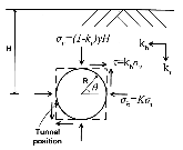
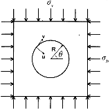
Consider a circular tunnel of radius R located sufficiently below the ground surface and subjected to horizontal and vertical accelerations from an earthquake loading as shown in Fig. 1. The stress state of the soil around the tunnel can be expressed as

 (1)
(1)
 (2)
(2)
 (3)
(3)
where σv and σh are the normal stresses, τ is the shear stress, kv and kh are the vertical and horizontal acceleration coefficients, K is the lateral earth pressure coefficient and γ is the unit weight of the soil over height H. By neglecting the effect of vertical acceleration, the stress state of the soil around the tunnel during an earthquake can be considered by the sum of the static loading of σv and σh, and seismic loading of τ, as shown in Fig. 2. Further the stress state due to static loading can be divided into isotropic σi and deviatoric σd parts. The seismic loading is equivalent to a compressive and a tensile free-field principal stresses at 45o with the direction of the pure shear. It is required to solve for the thrust and moment in the lining due to static and additional seismic loadings.
The shear stress can also be estimated as(Penzien and Wu, 1998),
 (4)
(4)
where γc is the average free-field shear strain of the soil over the depth 2R, which can be obtained from
 (5)
(5)
u(y,t) is the horizontal free-field ground displacement with depth y and time tc which produces the maximum shear-type deformation of the soil over the depth 2R of the intended tunnel, Es is the Young’s modulus of the soil, and νs is the Poisson’s ratio of the soil.
3. Previous analytical solutions
The existing analytical solutions for thrust Ts and moment Ms due to static loading can be found for two extreme conditions (Einstein and Schwartz, 1979): for the full-slip condition at the soil-lining interface,
 (6)
(6)
 (7)
(7)
where
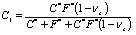 (8)
(8)
 (9)
(9)
and for the no-slip condition at the soil-lining interface,
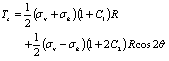 (10)
(10)
 (11)
(11)
where
 (12)
(12)
 (13)
(13)
 (14)
(14)
 (15)
(15)
C* and F* are compressibility and flexibility ratios, which are measures of the extensional and flexural stiffness, respectively, defined as
 (16)
(16)
 (17)
(17)
El, νl, Il and Al are the Young’s modulus, the Poisson’s ratio, the moment of inertia and the cross-sectional area of the lining, respectively.
4. Present analytical solutions
4.1 Static analysis
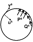
For convenience in analysis, the static loading condition in Fig. 2 will be separated into three cases: a circular cylindrical cavity subjected to excavation (Fig. 3(a)), a circular cylindrical lining subjected to contact stresses at the soil-lining interface (Fig. 3(b)), and a circular cylindrical cavity subjected to contact stresses at the soil-lining interface (Fig. 3(c)).
4.1.1 Interaction force and displacement distribution
(1) A cylindrical cavity subjected to excavation
If a circular tunnel is subjected to the static loading of σi and σd as shown in Fig. 3(a), the stresses around the cavity leads to the radial and circumferential displacement, u and v, respectively (Moore, 1994)
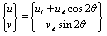 (18)
(18)
where
 (19)
(19)
 (20)
(20)
 ,
, (21,22)

Gs is the shear modulus of the soil. Subscripts i and d indicate isotropic and deviatoric components, respectively.
If the lining is considered in the cavity, then the radial and circumferential forces per unit circumference, P and Q, develop across the soil-lining interface. The soil experiences the forces Ps and Qs which lead to radial and circumferential displacements us and vs, while the lining is subjected to forces Pl and Ql leading to displacements ul and vl.
(2) A cylindrical lining subjected to contact stresses
The stress-displacement relations for the lining can be expressed as (Flügge, 1966; Einstein and Schwartz, 1979),
 (23)
(23)
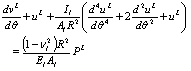 (24)
(24)
From Eq. (18) and using the following equations,
 (25a)
(25a)
 (25b)
(25b)
 (25c)
(25c)
 (25d)
(25d)
the relationship between displacements ul, vl and interaction forces Pl, Ql in the lining can be expressed using the influence matrix Il,
 (26)
(26)
 (27)
(27)
where
 (28)
(28)
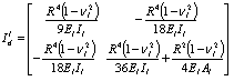 (29)
(29)
(3) A cylindrical cavity subjected to contact stresses
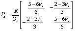
The response of a cylindrical cavity to a continuous cylindrical lining load can be obtained using the plane strain flexibility matrix Is, (Moore, 1994)
 (30)
(30)
 (31)
(31)
where
 (32)
(32)
 (33)
(33)
4.1.2 Soil-lining interaction
In numerical methods, interface elements have been used to allow the differential movement of the soil and the structure at the soil-structure interface (Day and Potts, 1994). In this study, elastic normal and shear stiffnesses, kn and ks, are used to simulate the differential movement at the soil-lining interface. Then, using the flexibility equations for soil and lining and introducing normal and shear stiffness ratios, Kn and Ks, the interaction forces can be evaluated for interface condition.
(a) Uniform response
For the uniform response of the soil-lining system,
the following equilibrium of interaction forces and
compatibility of displacements can be considered:
 (34)
(34)
 (35)
(35)
By substituting the appropriate equations in (18)~ (33) into (34)~(35), one can obtain
 (36)
(36)
Using the compressibility ratio C and the normal stiffness ratio Kn, defined as
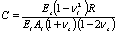 (37)
(37)
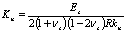 (38)
(38)
Eq. (36) can be rewritten as
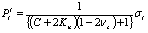 (39)
(39)
(b) Deviatoric response
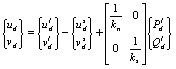
Consider the following equilibrium of interaction forces and compatibility of displacement for the deviatoric response of the soil-lining system,
 (40)
(40)
 (41)
(41)
 (42)
(42)
When kn→∞ and ks→∞, Eqs. (40)~(42) represent the no-slip interface condition. When kn→∞ and ks→0,  and
and  vanish, which means the lining is subjected to sliding along the interface.
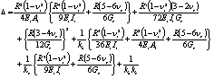
By substituting the appropriate equations in (18)~ (33) into (40)~(42), one can obtain
 (43)
(43)
where
 (44)
(44)
Using the flexibility ratio F and the shear stiffness ratio Ks, defined as
 (45)
(45)
 (46)
(46)
Eqs. (43) and (44) can be rewritten as
 (47)
(47)
where
 (48)
(48)
Note that when Kn=Ks=0, Eqs. (47) and (48) represent
the no-slip interface condition, whereas the case of
Kn=0 and Ks→∞ indicates the full-slip interface condition.
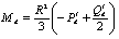
Then, the thrust and the moment in the lining due to static loading of σi and σd can be obtained:
 (49)
(49)
 (50)
(50)
where
 (51)
(51)
 (52)
(52)
 (53)
(53)
4.2 Seismic analysis
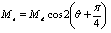
As mentioned in Section 2, the shear stress due to additional seismic loading is equivalent to a compressive and a tensile free-field principal stresses at 45o with the direction of the pure shear. So the thrust and moment due to additional seismic loading can be obtained by simply substituting τ for σd and cos2(θ+π/4) for cos2θ in Eqs. (49)~(53). However, since the shear stress is generated after the cavity is opened, the following σd is considered:
 (54)
(54)
Therefore, the thrust and the moment due to additional seismic loading can be obtained:
 (55)
(55)
 (56)
(56)
where subscript e indicates the solution for additional seismic loading.
5. Definition of stiffness ratios for interface element
In the previous researches (Burns and Richard, 1964; Höeg, 1968; Peck et al., 1972), the relative stiffness of the lining and the soil is characterized by two ratios (the compressibility ratio and the flexibility ratio). The compressibility ratio C is a measure of the extensional stiffness of the soil relative to that of the lining, while the flexibility ratio F is a measure of the flexural stiffness of the soil relative to that of the lining: (Peck et al., 1972)
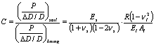 (57)
(57)
 (58)
(58)
In a similar way, the normal stiffness ratio and the shear stiffness ratio are introduced to characterize the relative stiffness of the soil and the interface element. The normal stiffness ratio Kn is obtained for a uniform external pressure,
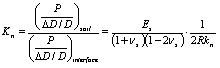 (59)
(59)
and the shear stiffness ratio Ks is obtained for a pure shear,
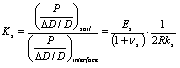 (60)
(60)
6. Effects of normal and shear stiffness ratios
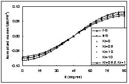
The interaction effect at the soil-lining interface is included using the normal and shear stiffness ratios. The effects of these ratios on the normalized thrust and the normalized moment are investigated using the values of νs=0.35,νl=0.15, C=1.0, F=1.0.
Figs. 4 and 5 show the results of normalized thrust and moment distributions with respect to Ks for K =0.5 and Kn=0, while the results for K=2.0 are shown in Figs. 6 and 7. For comparison, the results for full- slip (F-S) and no-slip (N-S) conditions, and the case of Kn=0.5 and Ks=1 are also shown in the figures. θ=90o indicates the tunnel crown, while θ=0 indicates the tunnel springline. As expected, the case of Kn=Ks=0 gives the same results as those of no-slip interface condition. The normalized thrust increases with the decrease of Ks from the full-slip condition to the no-slip condition. The normalized moment decreases as Ks decreases from the full-slip condition to the no-slip condition. While the shear stiffness ratio Ks can theoretically vary from zero to infinity, Figs. 4 to 7 show that the shear stiffness ratio seems to be limited to a certain range.

|
| |
Fig. 6. Normalized thrust (K=2.0, Kn=0). | Fig. 7. Normalized moment (K=2.0, Kn=0). | |
|
| |
Fig. 8. Normalized thrust (K=0.5, Ks=0). | Fig. 9. Normalized thrust (K=2.0, Ks=0). |

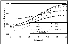
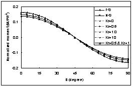

Figs. 8 and 9 show the results of normalized thrust
with respect to Kn for K=0.5 and 2.0 respectively, with Ks=0. The normalized thrust increases with the decrease of Kn. The normalized moment decreases as Kn increases.
7. Conclusions
Simple closed-form analytical solutions for thrust and moment in the lining of a deep and circular tunnel due to static and seismic loadings have been presented by considering the relations between displacements and interaction forces at the soil-lining interface. The normal stiffness ratio and the shear stiffness ratio are introduced as a means of defining interface element stiffness. Unlike the existing analytical solutions, which consider only two extreme conditions (the full-slip interface condition and the no-slip interface condition), new solutions allow the differential movement of the soil and the lining at the soil-lining interface.
The no-slip interface condition is one extreme case of Kn=Ks=0, whereas the full-slip interface condition is the other extreme case of Kn=0 and Ks→∞. The normalized thrust increases with the decrease of Kn and Ks. The normalized moment decreases with the decrease of Ks and the increase of Kn.