


1. Introduction
2. Numerical modeling
2.1 3-D model
2.2 Constitutive model
2.3 Train-induced vibration
3. Results
4. Conclusions
1. Introduction
Tunnel is one of the most important structures in transportation field to shorten the length of traffic routes and elapsing time. Nowadays, the progress and development of tunneling technology, the size and length of modern tunnel is getting larger and massive. Various innovative tunneling methods have been invented and shield tunneling is one of them. Shield tunneling is normally applied to soft, weathered rock and soil to enhance the stability with rapid excavation. A tunnel within loose and saturated granular soil is exposed to the liquefaction potential of surrounding soil; therefore, a dedicated analysis should be performed to secure the seismic stability of a tunnel.
A numerical analysis is one of the most important and convenient methods to investigate and predict the dynamic behavior of a tunnel. Do et al. (2014) performed a three dimensional numerical analysis on a shallow twin tunnel in soft ground and investigated the influence of the construction process between adjacent two tunnels. As a result, the simultaneous excavation of twin tunnels caused smaller structural forces and lining displacements, however, it could result in a higher surface settlement. Dias and Kastner (2013) simulated a slurry pressurized subway shield tunnel by two and three-dimensional analysis. Horizontal and vertical displacements during excavation were compared with the practical data, and three-dimensional analysis showed more effective and realistic results.
The dynamic behavior of tunnel is a problematic issue and hard to predict in field because of the nonlinear and time dependent responses, so the numerical simulation has been a useful tool for many years with the progress of the software technology. Cheng et al. (2014) examined the seismic response of the fluid-structure interaction (FSI) of an undersea tunnel in a broken fault zone during a bidirectional earthquake. The FSI model was created by the finite element method to account for the effects of seepage, dynamic liquid pressure, viscoelastic artificial boundary. The time dependent displacement and acceleration of tunnel structures were obtained and monitored during the earthquake. Azadi and Hosseini (2010) analyzed the effect of seismic behavior of shallow tunnels in liquefiable grounds by two-dimensional numerical simulation. Pore water pressure, effective stress, forces in the tunnel lining, surface displacement were calculated. The parametric studies were also performed with respect to the loading frequency, amplitude, vertical acceleration, lining material properties, lining thickness, etc. Guo and Ding (2005) performed a parallel numerical simulation for seismic response analysis of shield tunnel. A domain decomposition method was introduced to reduce the computer run time and the memory requirement in large-scale problems.
The environmental impact of vibrations due to railways is getting important on account of increasing public and social impact. Since the vibration and noise have been inevitable problems in a railway tunnel, great efforts have been made in the decades to invent numerical models for the prediction of ground vibrations from railways. Various numerical and analytical methods have been employed to simulate the coupled track-tunnel-soil system (Gupta et al., 2010).
Most studies focused on solving the train-track-soil interaction. Auersch (2005) has coupled a finite element model for a finite part of the track to a boundary element model for the soil. Gupta et al. (2008) have used the coupled periodic finite element-boundary element approach for predicting vibrations due to subway traffic in Beijing. This model exploits the invariance or periodicity of the system in the longitudinal direction using the Fourier or the Floquet transform to formulate the problem in the frequency- wave number domain.
In this study, a finite difference method was used to investigate the effect of train-induced vibration on the circumjacent soil. Especially, the liquefaction potential due to the propagation of the traffic vibration was analyzed by the numerical analysis.
2. Numerical modeling
2.1 3-D model
In order to analyze the dynamic behaviors of shield tunnel, a 3 dimensional model was built based on a dynamic finite difference method. The commercial code, FLAC3D was utilized for the numerical simulation.
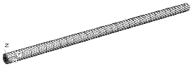
Fig. 1 describes the generated grid of 3D model and tunnel. The model size was 100 m in width, 200 m in length and 66.8 m in depth. The buried depth of the tunnel was 12.8 m. Note that the start and end area of the tunnel were reinforced by the jet grouting.

Analyses were performed in three stages. In the first stage, soil must reach the static equilibrium which represents the initial in-situ stress conditions. Therefore, a static analysis was conducted based on the material properties and static boundary conditions.
The second stage is the distribution of pore water pressure in the ground. The isometric fluid model was applied to simulate the saturated soil condition. In this study, water pressure was applied to the tunnel and the ground and the datum is ground surface. Note that this tunnel was not originally designed to be constructed under this condition.
The last stage is the implementation of the train- induced vibration load to the model. The variation of pore water pressure would be monitored to assess the liquefaction potential. The train-induced vibration was also calculated based on the design code and train specifications.
2.2 Constitutive model
The behavior of the generated 3-D model was assumed to be subjected to the elasto-perfectly plastic constitutive equations in the Mohr-Coulomb criterion. Thus, the Mohr-Coulomb model was adopted to perform the static analysis.
In order to estimate the liquefaction potential of the model, the soil model should enable to consider the change and development of excess pore pressure under the dynamic analysis. The Finn model (1976) which is proposed to estimate the change of excess pore pressure was applied in the dynamic analysis. The Finn model continuously updates the pore water pressure using equations which relate pore water pressures to dynamic shear strain history. Martin et al. (1975) supplied the following empirical equation that relates the increment of volume decrease,  , to the cyclic shear strain amplitude,
  .
.

where,  ,
,  ,
,  , and
, and  are the constant. In practical analyses, the relationships of those constants can be shown as follows:



where,  is relative density of soil.
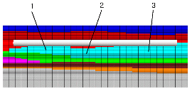
Rayleigh damping which can consider the mass and stiffness proportional damping was used in the present model. Fixed boundary condition was applied the edge of the generated grid in the static analysis, then, the free-field boundary was imposed in the lateral and longitudinal direction in the dynamic analysis to minimize the reflection of scattered waves from the dynamic source in the grid. The material properties are provided in Table 1, and the applied to the model by grouping as shown in Fig. 2.
2.3 Train-induced vibration
The vertical vibrating load by a train can be calculated by the design velocity, velocity impact factor,  , axial load of a train, and trackbed pressure. Table 2 displays a train specification for estimating the train-induced vibration.
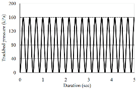
The vibrating load can be expressed by a sinusoidal shape and its frequency is calculated by the Equation (5).

where,  is the frequency,
  is the design velocity of a train, and
  is the wheel distance of each compartment. Therefore, the frequency is 3.5 Hz based on the Table 2. The vibration loading type is sinusoidal by a general cosine function.
Next step to estimate the vibrating load is to determine the maximum trackbed pressure,  , as shown in Table 3.
where,  (=0.4 in general) is the reduction factor which considers the distribution effect of axial load through the trackbed, A is the effective area of a reinforced concrete (RC) sleeper. Fig. 3 displays the time history of trackbed pressure calculated in this study.

3. Results

 (kN)
(kN) (kN)
(kN) ×
×
 (kN)
(kN) ×
×
 (kPa)
(kPa) /A
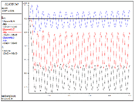
/AFig. 4 shows variations of the pore water pressure at different monitoring points 1 to 3 as shown in Fig. 2. The amount of excess pore water pressure generated by the dynamic loading was obtained and showed larger values at the beginning area of the tunnel, point 1. The tendency of pore water generation is normally affected by the site condition such as depth of bedrock, permeability, relative density, etc, therefore, it is difficult to estimate the excess pore water pressure quantitatively through wide area. Numerical analysis enables to estimate pore water pressure through wide area promptly, and the potential of liquefaction can be predicted based on the pore water pressure measurement. Table 4 shows the results.
Fig. 5 displays variations of the vertical displacement of the crown. Maximum displacement of around 2.7 mm was estimated at the point 3, because the thickness of the soft layer is largest around the point 3, however, the difference of the displacement was not severe.
4. Conclusions
3D numerical analysis on the shield tunnel was performed to consider the effect of train-induced vibration. Here are the main achieved results:
1.Train-induced vibrating load was calculated by a few parameters such as design velocity, velocity impact factor,  , axial load of a train, and trackbed pressure with sine equation, accordingly, a sinusoidal shape of loading were obtained and applied to the analysis.
2.The variations of pore water pressure were obtained and analyzed to estimate the liquefaction potential. The amount of excess pore water pressure generated by the dynamic loading was obtained and showed larger values at the beginning area of the tunnel, point 1.
3.Maximum crown displacement of 2.7 mm was estimated at the point 3, because the thickness of the soft layer is largest around the point 3, however, the difference of the displacement was not severe.
4.It is confirmed that the generation of excess pore water pressure by train-induced vibrating load, however, the amount does not meaningfully affect the potential of liquefaction. Note that the liquefaction potential is variable according to the ground conditions.