Technical Paper

Journal of Korean Tunnelling and Underground Space Association. 31 March 2023. 43-63
https://doi.org/10.9711/KTAJ.2023.25.2.043

ABSTRACT


MAIN

  • 1. 서 론

  • 2. 수치해석

  •   2.1 검토 개요

  •   2.2 검토방법 및 검토 조건

  •   2.3 터널 안정성 검토

  •   2.4 안정성 검토

  • 3. 결 론

1. 서 론

현재 도심지의 인구 집중으로 지상 구조물의 포화상태로 지하구조물의 개발이 중요시되고 있다. 또한 인구 밀집화가 일어남에 따라 지상의 교통이 원활하게 돌아가지 못하고 있다. 이에 따라 국내에는 지하를 이용한 교통 터널 시공 및 설계를 활발하게 진행하는 추세이다. 그러나 인구의 밀집만큼 건축물 또한 밀집되어있어 시공을 진행하는데 환경적으로나 주변구조물의 간섭이나, 민원 등으로 시공하는데 어려움이 있다. 민원 발생은 대처기간의 소요로 인하여 예상치 못한 공기 지연 및 공사비 증가를 야기한다(Sin et al., 2009). 국내 터널을 시공할 때는 안전성이 무엇보다 중요하기 때문에 안전하면서도 경제적으로 시공하여야 한다. 이를 위해서 현지 지반 조건에 가장 적합한 지보패턴 및 굴착공법이 적용되어야 한다(Nam, 1999). 또한 국내의 근접 병설 터널에 관한 연구는 활발히 진행 중이다.

Sin and Kim (2010)은 충분한 이격거리를 확보한 병설 터널의 거동특성과 구별되는 거동특성을 보이는 근접 병설 터널의 체계적인 안정성 평가방법을 대단면 근접 병설 터널 설계사례를 중심으로 연구를 진행하였고, Kim and Kim (2007)은 암반 필라부 보강공법의 적정성 검토 및 향후 근접 병설 터널에서의 암반 필라 안정성 확보를 위한 개선방안을 제안하였다. Ahn and Park (2021)은 토사지반에서 대구경 강관추진을 활용한 횡갱 굴착 공법의 시공 중 유의사항을 소개하고 시공 후 계측결과를 분석하였다. 이처럼 병설 터널에 대한 연구는 안정성 평가방법 및 개선방안을 제안하는데 국한되어있다. 따라서 지하 공간 설계 기술이 많이 발전된 현 상황으로는 터널의 단면이 큰 장대터널로 시공되는 경우가 많다. 이때 일반적으로 사용되는 병설 터널로는 크게 일반 병설 터널과 2아치 터널로 이루어져 있다. 하지만 이 두 가지는 모든 하중이 중앙벽체에 집중되며, 누수현상이 자주 발생하고, 주변구조물의 간섭영향 범위가 증가하며, 터널의 공정이 복잡해지는 등 공기 및 공사비가 증가하는 문제점이 있다. 또한 발파 시 선 ‧ 후 터널 및 필라부에 균열이 발생하는 문제점이 있다. 이러한 문제점의 해결을 위해 근접 병설 터널 필라부 보강공법의 적용이 증대되고 있는 추세이다. 근접 병설 터널의 경우 터널간 거리를 충분히 확보하고 있는 일반적인 터널에 비해 안정성 측면에서 불리한 점이 많은데, 특히 좁은 필라부의 강도를 증가시키기 위하여 다양한 방법을 적용하고 있으나 필라부의 적정한 거동특성을 반영한 필라부 보강공법은 많지 않은 실정이다. 그러므로 실질적인 거동 메커니즘의 수치 해석적 검토를 진행하였다.

2. 수치해석

2.1 검토 개요

병렬터널이나 터널의 분기부 및 합류부에 있어 터널간의 간격은 터널상부의 민원 영향 범위를 최소화하기 위하여 가능하면 가깝게 하는게 합리적이다. 그러나 터널의 필라부는 응력이 집중되는 부분으로 간격이 가까울 경우 보강이 요구된다. Kim et al. (2022)은 보강법은 다양하지만 이 연구 대상공법인 현장적용성 및 안정성에서 우수하다고 판단되어 개발된 프리스트레스와 그라우팅을 이용한 터널 필라부 보강공법에 대한 축소모형 실험을 진행하였다. 이를 바탕으로 터널 굴착 시 보강공법의 효과를 파악하기 위하여 수치해석을 수행하였다. 수치해석은 크게 보강 시 PC강연선을 이용해 프리스트레스를 준 보강과 타이볼트를 이용해 프리스트레스를 준 보강 및 무보강시로 나누어 진행하였다.

2.2 검토방법 및 검토 조건

2.2.1 검토방법 선정

안정성 검토 방법 중 지반공학적 방법은 지반과 구조물을 직접 모델링하고 시공순서 및 지반과 구조물의 상호작용 등을 고려하므로 굴착에 따른 지반의 응력 및 변형을 고려할 수 있다. 또한 컴퓨터의 발달에 따라 그 적용 범위가 더욱 넓어지고 있으며, 다양한 수치해석 기법들의 적용성이 향상되면서 지중구조물의 안정성 평가 방법의 대다수를 차지하고 있다.

본 과업의 터널 안정성 검토에서 사용한 프로그램은 MIDAS GTX NX로 연속체 해석(유한요소법)에 해당하는 프로그램으로, 정적 및 동적 평형방정식, 연속방정식을 선택하여 연속체 공간을 유한요소로 생성하고 강성행렬에 의해 구해진 변위벡터를 적합 방정식 및 구성 방정식을 통해 응력-변형률 수렴해를 구한다. 정해석, 침투해석, 압밀해석, 고유치해석, 응답스펙트럼 해석 및 동해석의 다양한 해석분야에 적용 가능한 프로그램이다. 적용이론은 유한요소법(Finite Element Method, FEM)을 기반으로 운용되며 복잡한 지형형상과 지반 조건 및 시공단계 모사를 위한 적용성이 우수하여 이 프로그램을 적용하였다.

2.2.2 검토조건 선정

수치해석의 해석영역은 굴착에 의한 영향이 최소가 될 수 있는 충분한 범위로 설정하여야 한다. 터널 좌우 측방 해석범위는 지반의 초기응력 상태(측압계수, K0)에 영향을 받으며, 측압계수가 클수록 영향범위는 증가한다. 또한 해석범위는 터널의 형상, 터널의 단면 크기 및 대상지반의 지질특성 등의 영향을 받는 것으로 알려져 있다. 따라서, 터널 굴착에 따른 지반의 응력 영향권을 모두 포함하는 영역을 해석 영역으로 설정하여야 한다. Kulhawy (1974)는 경계조건이 터널해석 결과에 영향을 미치지 않게 하기 위해서는 해석의 범위가 터널반경의 6배(터널 직경의 3배) 이상 떨어져야 한다는 주장을 하였다. 다음 Table 1은 일반적으로 제시되는 해석영역의 범위를 나타내었다.

Table 1.

The range of numerical analysis area

Classification Kulhawy
(1974)
Road design
guidelines
(KEC, 1992)
Tunnel standard
specification
(MOLIT, 1992)
Working group on
highway tunnel design
(KEC, 1995)
Analysis area
(D: diameter,
H: height)
• Upper: The ground
surface
• Side: 3.0D
• Bottom: 3.0D
• Upper: The ground
surface
• Side: 1.5D
• Bottom: 1.0D
• Upper: The ground
surface
• Side: 2.5D
• Bottom: 1.5H
• Upper: The ground
surface
• Side: 4.0D or higher
• Bottom: 3.0H or higher

본 검토 시 해석영역은 좌우 및 하부에 굴착폭의 4배 이상 해석영역을 적용하였다.다음 Table 2와 같이 좌우 경계 및 바닥면에 수평 및 연직롤러를 적용하고 양단 모서리는 힌지조건을 적용하였다.

Table 2.

Analysis area and boundary conditions

Classification Location Applied analysis area and boundary conditions
Analysis area Top of the tunnel Applied more than 1.0D at the top of the tunnel
Side of the tunnel Apply 4.0D or higher in tunnel sidewalls
Under the tunnel Apply 4.0D or higher in the tunnel floor
Boundary
condition
Left and right boundary Roller conditions
(horizontal displacement: constraint, vertical displacement: allowable)
Lower boundary Roller conditions
(horizontal displacement: allowable, vertical displacement: constraint)
Lower both ends Hinge condition (horizontal and vertical displacement: constraint)

지반 내의 초기응력은 일반적으로 수직응력과 수평응력으로 표현되며 수직응력에 대한 수평응력의 비율을 측압계수로 정의한다. 본 수치해석 검토는 풍화암에 대하여 진행하였으며 1.0을 적용하여 진행하였다.

본 검토에 적용된 터널의 지보재 특성치는 Table 3과 같다.

Table 3.

Characteristics of tunnel support material

Classification Unit weight
(kN/m3)
Modulus of elasticity
(MPa)
Poisson’s ratio Note
Shotcrete Ductility 20.0 5,000 0.20 fck = 10 MPa
Hardness 15,000 0.20 fck = 35 MPa
PC stranded wire 78.5 200,000 - D = 15.2 mm
Rock bolt D25/SD350

터널 안정성 평가 시 적용된 숏크리트 허용응력은 Table 4와 같다.

Table 4.

Allowable stress for shotcrete

Classification Allowable stress Note
Shotcrete Allowable compressive stress 0.4*fck 14 MPa fck = 35 MPa
Rock bolt Allowable axial force 0.5*fy*A 88.7 kN fy = 350 MPa

현재 대부분의 강관다단 설계법은 등가물성으로 보고 설계를 수행한다. 최근 연구 결과에 의하면 최적의 등가물성 산정식은 강관과 그라우팅은 직렬 연결된 복합체이며, 원지반과 병렬 연결되어 복합거동하는 경우가 최적이다. 다음 Table 5는 그라우팅 특성치를 나타낸 것이다.

Table 5.

Grouting characteristics

Classification Unit weight
(kN/m3)
Cohesion
(kN/m2)
Internal
friction angle
(°)
Modulus of
elasticity
(MPa)
Poisson’s
ratio
Reinforcement grouting at the
top of the tunnel
21 216.18 30 911.14 0.30
Pillar reinforcement grouting 21 126.30 30 437.44 0.30

터널 안정성 검토에서는 Table 6과 같이 하중분담율을 적용하였다.

Table 6.

Applied load distribution factors

Classification Load sharing ratio (%)
Excavation stage (α) Soft shotcrete (β) Hard shotcrete (γ)
Upper 40 20 40
Bottom 40 20 40

수치해석에 적용된 설계지반정수는 다음 Table 7과 같다.

Table 7.

Applied ground characteristics

Classification Unit weight
(kN/m3)
Cohesion
(kPa)
Internal
friction angle
(°)
Modulus of
elasticity
(MPa)
Poisson’s
ratio
Weathered rock 21.0 35.0 33.0 300 0.30
Class V 22.0 150.0 30.0 700 0.30

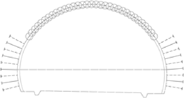
실내 축소모형 실험 결과를 바탕으로 하여 터널폭(D = 16.34 m)의 병설터널을 0.5D 간격으로 Fig. 1과 같이 모델링하여 수치해석을 진행하였다.

https://cdn.apub.kr/journalsite/sites/kta/2023-025-02/N0550250201/images/kta_2023_252_43_F1.jpg
Fig. 1.

Modeling diagram

공법의 비교분석을 위하여 Table 8과 같이 PC강연선 + 강관보강 그라우팅 + 프리스트레스의 경우와 타이볼트 + 프리스트레스의 경우, 무보강의 경우 세 가지의 공법으로 수치해석을 진행하였다. 각 Case별 시공단계에 따른 수치해석 데이터를 토대로 터널 내공변위 및 부재력 필라부 응력변화 및 필라부에 작용하는 긴장력의 강도에 따른 변화 등을 분석하였다.

Table 8.

Numerical analysis case

Classification Pillar reinforcement contents
Case 1 PC stranded wire + Steel pipe reinforcement grouting + Prestress
Case 2 Tie bolt + Prestress
Case 3 No reinforcement

적용된 지보패턴은 다음 Table 9와 같다.

Table 9.

Support pattern

Applied support pattern
https://cdn.apub.kr/journalsite/sites/kta/2023-025-02/N0550250201/images/kta_2023_252_43_T1.jpg Excavation method Top and bottom division (ring cut if necessary)
Advance 0.8 m
Shotcrete High-strength steel fiber reinforcement (25 cm)
Rock bolt L = 5 m, 0.8 m (longitudinal) / 1.2 m (transverse)
Auxiliary method Large diameter advanced reinforcement grouting 120° or
direct drilling advanced reinforcement grouting 120°

2.3 터널 안정성 검토

2.3.1 PC강연선 + 강관보강 그라우팅 + 프리스트레스

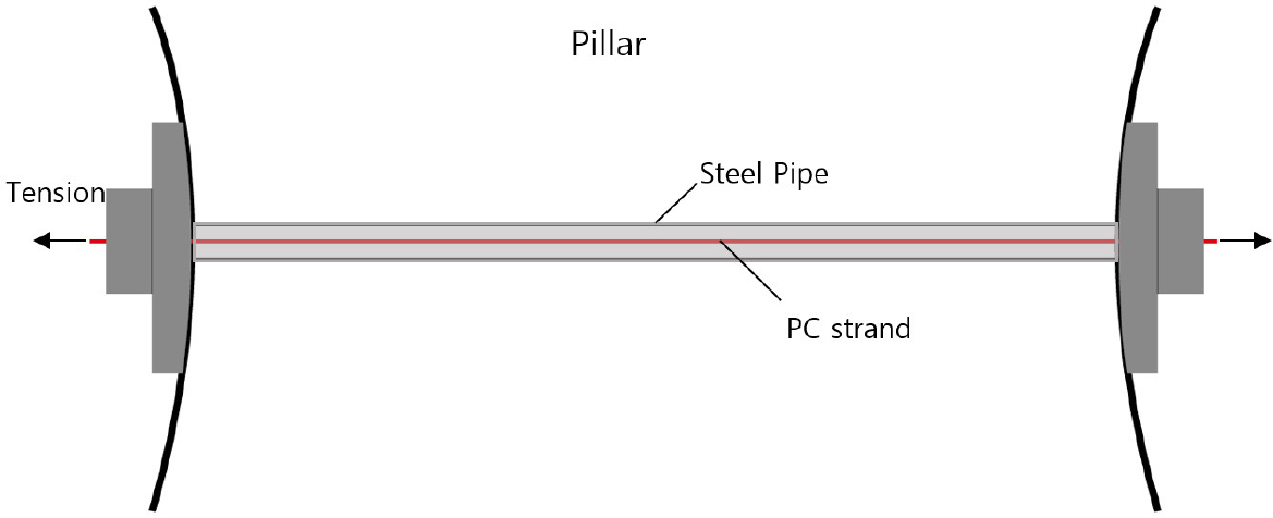
다음 Fig. 2는 PC강연선 + 강관보강 그라우팅 + 프리스트레스(150 kN) 보강 시 해석 모델링도이며, Fig. 3은 개요도이다.

https://cdn.apub.kr/journalsite/sites/kta/2023-025-02/N0550250201/images/kta_2023_252_43_F2.jpg
Fig. 2.

PC strand reinforcement analysis modeling diagram

https://cdn.apub.kr/journalsite/sites/kta/2023-025-02/N0550250201/images/kta_2023_252_43_F3.jpg
Fig. 3.

PC strand reinforcement schematic diagram

해석 순서는 다음 Table 10과 같다.

Table 10.

Pillar part PC stranded wire reinforcement analysis sequence

Construction stage Construction details
Step 1 Original ground
Step 2 Displacement initialization
Step 3 Left tunnel upper excavation and steel pipe reinforcement
Step 4 Upper half soft shotcrete + Upper half rock bolt construction + Upper half
(steel pipe + PC steel wire + grout) construction and temporary tensioning
Step 5 Upper hard shotcrete
Step 6 Left tunnel lower half excavation
Step 7 Lower half soft shotcrete + Lower half rock bolt construction + Lower half
(steel pipe + PC steel wire + grout) construction and temporary tensioning
Step 8 Lower half hard shotcrete
Step 9 Right tunnel upper half excavation and steel pipe reinforcement
Step 10 Upper half soft shotcrete + Upper half rock bolt construction + Upper half PC strand tension
Step 11 Upper hard shotcrete
Step 12 Right tunnel lower half excavation
Step 13 Lower half soft shotcrete + Lower half rock bolt construction + Lower half PC strand tension
Step 14 Lower half hard shotcrete

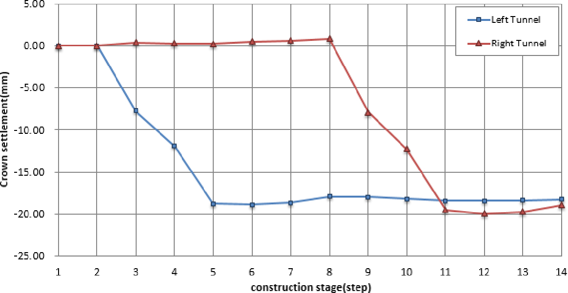
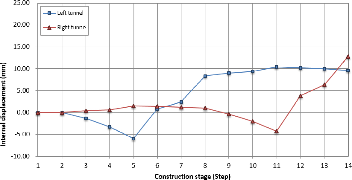
필라부 강관 + PC강연선 보강 패턴의 좌우 터널 변위 검토결과, 최대 천단침하는 각각 -18.870 mm, -19.947 mm, 최대 내공변위는 각각 10.420 mm, 12.783 mm가 발생하였다. 다음 Table 11은 강관 + PC강연선 보강 패턴의 변위 결과이다.

Table 11.

Pillar PC stranded wire reinforcement displacement result

Construction stage Crown settlement (mm) Internal displacement (mm)
Left Right Left Right
Step1 0.000 0.000 0.000 0.000
Step 2 0.000 0.000 0.000 0.000
Step 3 -7.701 0.426 -1.305 0.452
Step 4 -11.881 0.286 -3.340 0.640
Step 5 -18.746 0.236 -5.918 1.522
Step 6 -18.870 0.557 0.846 1.418
Step 7 -18.641 0.635 2.405 1.244
Step 8 -17.900 0.871 8.368 1.075
Step 9 -17.956 -7.903 8.982 -0.315
Step 10 -18.165 -12.229 9.401 -1.990
Step 11 -18.374 -19.476 10.420 -4.235
Step 12 -18.385 -19.947 10.199 3.754
Step 13 -18.343 -19.693 10.021 6.330
Step 14 -18.212 -18.912 9.603 12.783
Maximum value -18.870 -19.947 10.420 12.783

Inward displacement is the displacement of the left and right horizontal displacement, and the sign is crown settlement: downward↓(-), and internal displacement: inward direction→(+)

다음 Fig. 4는 천단침하 발생 경향, Fig. 5는 내공변위 발생 그래프이다.

https://cdn.apub.kr/journalsite/sites/kta/2023-025-02/N0550250201/images/kta_2023_252_43_F4.jpg
Fig. 4.

Tendency of crown settlement of reinforcement PC stranded wire

https://cdn.apub.kr/journalsite/sites/kta/2023-025-02/N0550250201/images/kta_2023_252_43_F5.jpg
Fig. 5.

Tendency of internal displacement of PC stranded wire reinforcement

필라부 강관 + PC강연선 보강 패턴의 좌우 터널 부재력 검토결과, 숏크리트 최대 압축응력은 각각 9.769 MPa, 8.894 MPa (<14 MPa, O.K), 록볼트 최대 축력은 각각 85.903 kN, 85.903 kN (<88.7 kN, O.K)이 발생하여 터널의 안정성이 확보되는 것으로 검토되었다. 다음 Table 12는 부재력 검토 결과이다.

Table 12.

Shotcrete compressive stress and rock bolt axial force results

Construction stage Shotcrete compressive stress (MPa) Rock bolt axial force (kN)
Left Right Left Right
Step 1 - - - -
Step 2 - - - -
Step 3 - - - -
Step 4 2.295 - 38.480 -
Step 5 6.327 - 85.903 -
Step 6 6.170 - 85.903 -
Step 7 6.333 - 85.903 -
Step 8 9.028 - 85.903 -
Step 9 9.160 - 85.509 -
Step 10 9.235 2.017 85.274 41.681
Step 11 9.617 7.875 84.785 85.903
Step 12 9.765 7.495 84.743 85.903
Step 13 9.769 7.446 84.757 85.903
Step 14 9.752 8.984 84.807 85.903
Maximum value 9.769 8.984 85.903 85.903
Allowable value 14 88.7
Evaluation O.K O.K O.K O.K

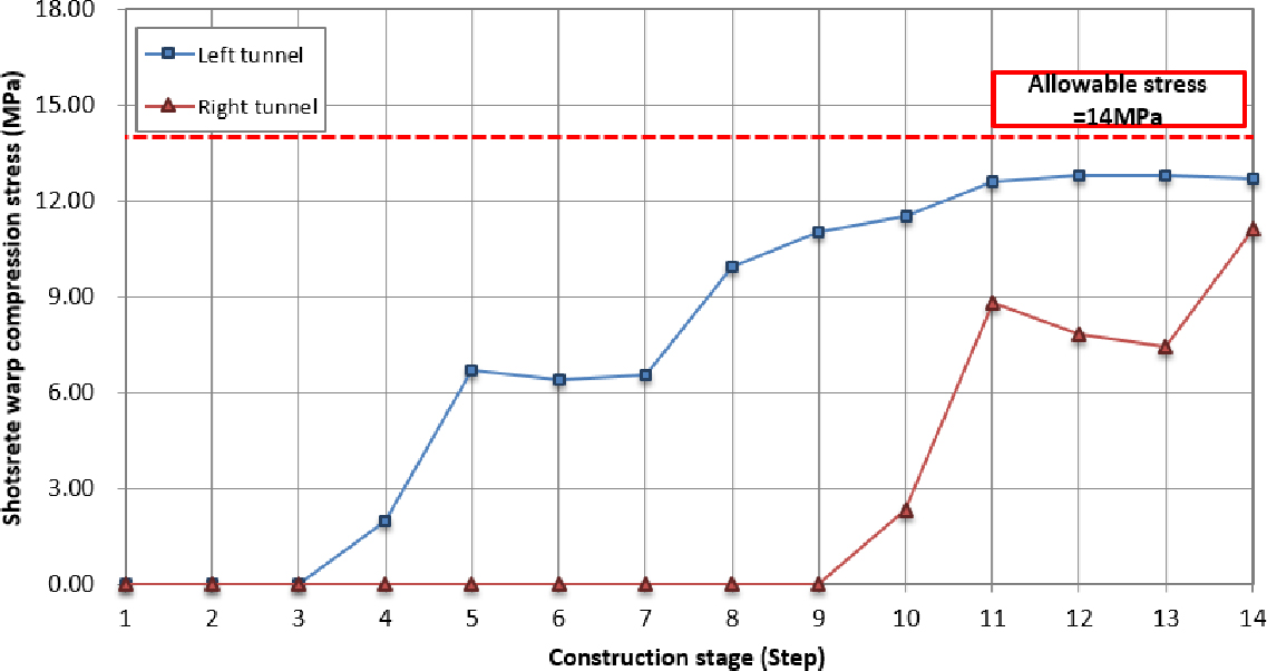
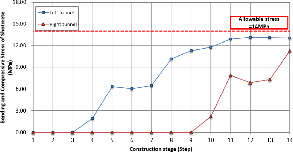
다음 Figs. 6 and 7은 강관 + PC강연선 보강 패턴의 숏크리트 압축응력, 숏크리트 전단응력 및 록볼트 축력 경향 그래프이다.

https://cdn.apub.kr/journalsite/sites/kta/2023-025-02/N0550250201/images/kta_2023_252_43_F6.jpg
Fig. 6.

Tendency of bending and compressive stress in shotcrete reinforcement with PC stranded wire

https://cdn.apub.kr/journalsite/sites/kta/2023-025-02/N0550250201/images/kta_2023_252_43_F7.jpg
Fig. 7.

Tendency of occurrence of axial force in the reinforcement rock bolt of PC stranded wire

2.3.2 필라부 타이볼트 보강

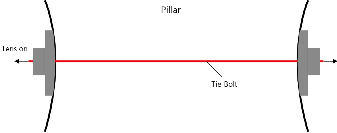
다음 Fig. 8은 타이볼트 + 프리스트레스(150 kN) 보강 시 해석 모델링도이며, Fig. 9는 개요도이다.

https://cdn.apub.kr/journalsite/sites/kta/2023-025-02/N0550250201/images/kta_2023_252_43_F8.jpg
Fig. 8.

Tie bolt reinforcement analysis modeling diagram

https://cdn.apub.kr/journalsite/sites/kta/2023-025-02/N0550250201/images/kta_2023_252_43_F9.jpg
Fig. 9.

Tie bolt reinforcement schematic diagram

해석 순서는 다음 Table 13과 같다.

Table 13.

Tie bolt reinforcement analysis sequence

Construction stage Construction details
Step 1 Original ground
Step 2 Displacement initialization
Step 3 Left tunnel upper excavation and steel pipe reinforcement
Step 4 Upper half soft shotcrete + Upper half rock bolt construction
+ Upper half tie bolt construction and tensioning
Step 5 Upper hard shotcrete
Step 6 Left tunnel lower half excavation
Step 7 Lower half soft shotcrete + Lower half rock bolt construction
+ Lower half tie bolt construction and tensioning
Step 8 Lower half hard shotcrete
Step 9 Right tunnel upper half excavation and steel pipe reinforcement
Step 10 Upper half soft shotcrete + Upper half rock bolt construction + Upper half tie bolt tension
Step 11 Upper hard shotcrete
Step 12 Right tunnel lower half excavation
Step 13 Lower half soft shotcrete + Lower half rock bolt construction + Lower half tie bolt tension
Step 14 Lower half hard shotcrete

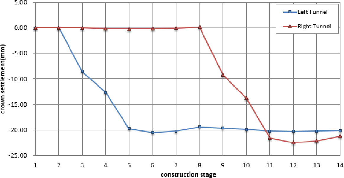
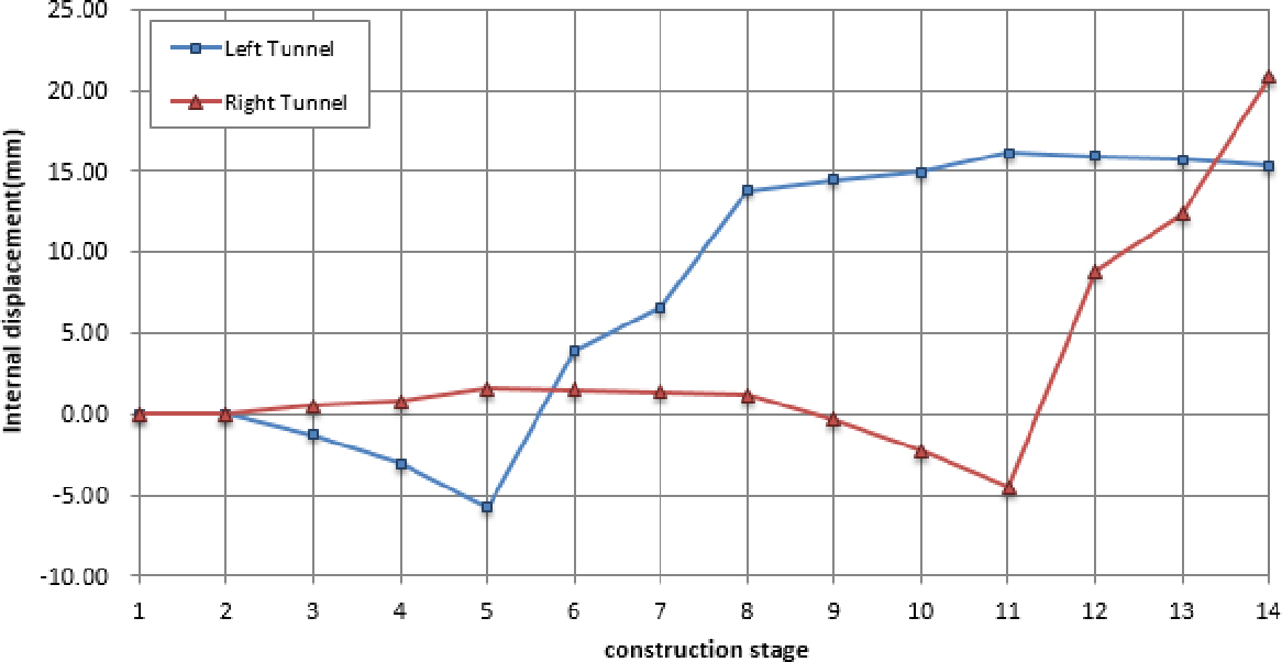
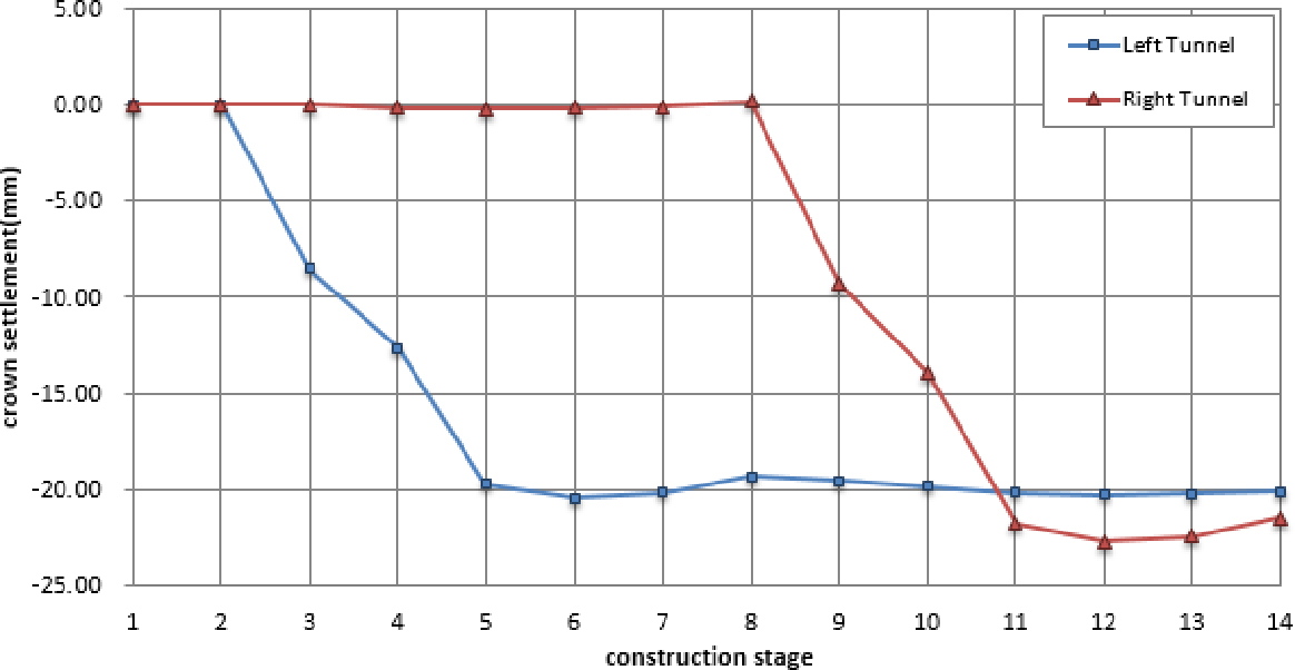
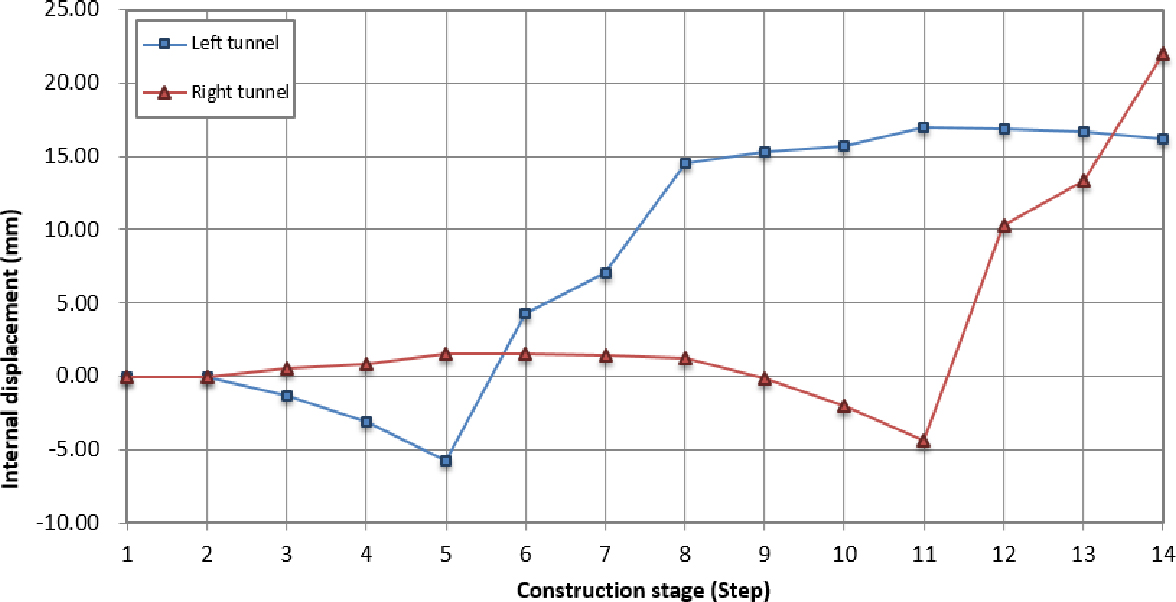
필라부 타이볼트 보강 패턴의 좌우 터널 변위 검토결과, 최대 천단침하는 각각 -20.461 mm, -22.381 mm 최대 내공변위는 각각 16.112 mm, 20.858 mm가 발생한다. 다음 Table 14는 필라부 타이볼트 보강 패턴의 변위 결과이다.

Table 14.

Tie bolt reinforcement displacement results

Construction stage Sinking of heaven (mm) Internal displacement (mm)
Left Right Left Right
Step 1 0.000 0.000 0.000 0.000
Step 2 0.000 0.000 0.000 0.000
Step 3 -8.483 0.022 -1.280 0.518
Step 4 -12.633 -0.132 -3.053 0.815
Step 5 -19.707 -0.202 -5.729 1.574
Step 6 -20.461 -0.139 3.931 1.517
Step 7 -20.196 -0.047 6.619 1.420
Step 8 -19.359 0.204 13.838 1.208
Step 9 -19.858 -9.175 14.507 -0.299
Step 10 -20.210 -13.733 14.953 -2.229
Step 11 -20.282 -21.479 16.112 -4.482
Step 12 -20.282 -22.381 15.948 8.841
Step 13 -20.231 -22.083 15.764 12.394
Step 14 -20.079 -21.157 15.345 20.858
Maximum value -20.461 -22.381 16.112 20.858

Inward displacement is the displacement of the left and right horizontal displacements, and the sign is crown settlement: downward↓(-), and internal displacement: inward direction→(+)

다음 Fig. 10은 천단침하 발생 경향, Fig. 11은 내공변위 발생 그래프이다.

https://cdn.apub.kr/journalsite/sites/kta/2023-025-02/N0550250201/images/kta_2023_252_43_F10.jpg
Fig. 10.

Tendency of crown settlement of tie bolt reinforcement

https://cdn.apub.kr/journalsite/sites/kta/2023-025-02/N0550250201/images/kta_2023_252_43_F11.jpg
Fig. 11.

Tendency of internal displacement of tie bolt reinforcement

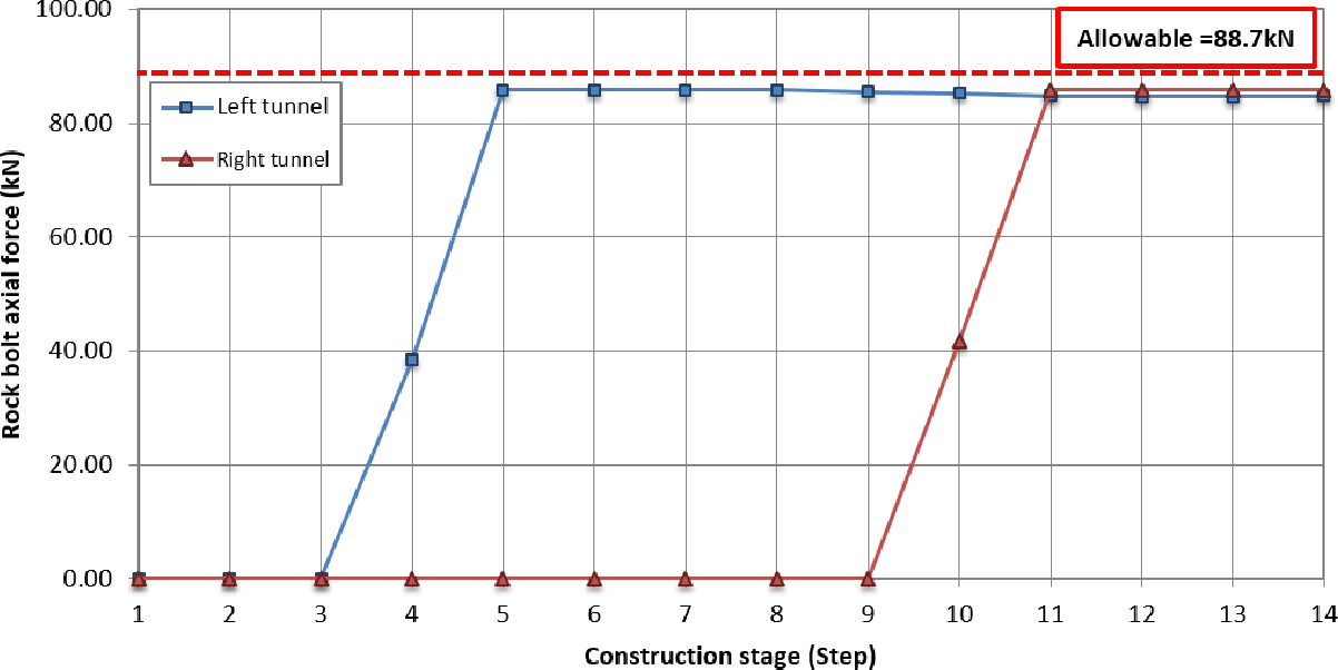
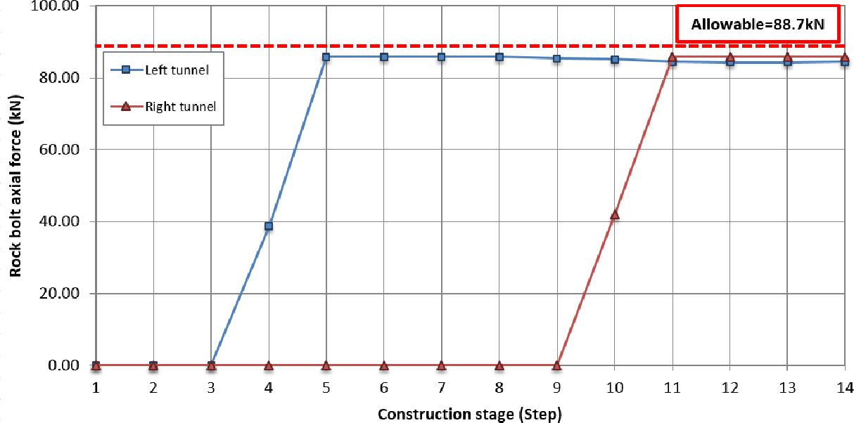
필라부 타이볼트 보강 패턴의 좌우 터널 부재력 검토결과, 숏크리트 최대 압축응력은 각각 12.805 MPa, 11.127 MPa (<14 MPa, O.K), 록볼트 최대 축력은 각각 85.903 kN, 85.903 kN (<88.7 kN, O.K)이 발생하여 터널의 안정성이 확보되는 것으로 검토되었다. 다음 Table 15는 부재력 검토 결과이다.

Table 15.

Shotcrete compressive stress and rock bolt axial force results

Construction stage Shotcrete compressive stress (MPa) Rock bolt axial force (kN)
Left Right Left Right
Step 1 - - - -
Step 2 - - - -
Step 3 - - - -
Step 4 1.987 - 33.605 -
Step 5 6.695 - 85.903 -
Step 6 6.419 - 85.903 -
Step 7 6.556 - 85.903 -
Step 8 9.932 - 85.903 -
Step 9 11.018 - 85.413 -
Step 10 11.540 2.351 85.140 41.899
Step 11 12.595 8.818 84.518 85.903
Step 12 12.805 7.812 84.374 85.903
Step 13 12.785 7.452 84.392 85.903
Step 14 12.716 11.127 84.456 85.903
Maximum value 12.805 11.127 85.903 85.903
Allowable value 14 88.7
Evaluation O.K O.K O.K O.K

다음 Figs. 12 and 13은 타이볼트 보강 패턴의 숏크리트 압축응력, 숏크리트 전단응력 및 록볼트 축력 경향 그래프이다.

https://cdn.apub.kr/journalsite/sites/kta/2023-025-02/N0550250201/images/kta_2023_252_43_F12.jpg
Fig. 12.

Tie bolt reinforcement shotcrete bending and compressive stress generation tendency

https://cdn.apub.kr/journalsite/sites/kta/2023-025-02/N0550250201/images/kta_2023_252_43_F13.jpg
Fig. 13.

Tie bolt reinforcement rock bolt axial force generation tendency

2.3.3 필라부 무보강

다음 Fig. 14는 무보강 시 해석 모델링도이다.

https://cdn.apub.kr/journalsite/sites/kta/2023-025-02/N0550250201/images/kta_2023_252_43_F14.jpg
Fig. 14.

Unreinforced analysis modeling diagram

해석 순서는 다음 Table 16과 같다.

Table 16.

Analysis sequence without reinforcement

Construction stage Construction details
Step 1 Original ground
Step 2 Displacement initialization
Step 3 Left tunnel upper excavation and steel pipe reinforcement
Step 4 Upper half soft shotcrete + Upper half rock bolt construction
Step 5 Upper hard shotcrete
Step 6 Left tunnel lower half excavation
Step 7 Lower half soft shotcrete + Lower half rock bolt construction
Step 8 Lower half hard shotcrete
Step 9 Right tunnel upper half excavation and steel pipe reinforcement
Step 10 Upper half soft shotcrete + Upper half rock bolt construction
Step 11 Upper hard shotcrete
Step 12 Right tunnel lower half excavation
Step 13 Lower half soft shotcrete + Lower half rock bolt construction
Step 14 Lower half hard shotcrete

필라부 무보강 패턴의 좌우 터널 변위 검토결과, 최대 천단침하는 각각 -20.428 mm, -22.710 mm 최대 내공변위는 각각 16.939 mm, 22.039 mm가 발생한다. 다음 Table 17은 무보강 패턴의 변위 결과이다.

Table 17.

Result of pillar unreinforced displacement

Construction stage Crown settlement (mm) Internal displacement (mm)
Left Right Left Right
Step 1 0.000 0.000 0.000 0.000
Step 2 0.000 0.000 0.000 0.000
Step 3 -8.483 0.022 -1.280 0.513
Step 4 -12.626 -0.134 -3.064 0.814
Step 5 -19.686 -0.210 -5.789 1.576
Step 6 -20.428 -0.153 4.261 1.542
Step 7 -20.160 -0.060 7.012 1.456
Step 8 -19.302 0.195 14.503 1.270
Step 9 -19.543 -9.322 15.262 -0.107
Step 10 -19.811 -13.863 15.712 -2.038
Step 11 -20.165 -21.740 16.939 -4.400
Step 12 -20.268 -22.710 16.846 10.321
Step 13 -20.228 -22.411 16.647 13.331
Step 14 -20.079 -21.452 16.227 22.039
Maximum value -20.428 -22.710 16.939 22.039

Inward displacement is the displacement of the left and right horizontal displacements, and the sign is crown settlement: downward↓(-), and internal displacement: inward direction→(+)

다음 Fig. 15는 천단침하 발생 경향, Fig. 16은 내공변위 발생 그래프이다.

https://cdn.apub.kr/journalsite/sites/kta/2023-025-02/N0550250201/images/kta_2023_252_43_F15.jpg
Fig. 15.

Tendency of crown settlement of non-reinforcement case

https://cdn.apub.kr/journalsite/sites/kta/2023-025-02/N0550250201/images/kta_2023_252_43_F16.jpg
Fig. 16.

Tendency of non-reinforced internal displacement

필라부 무보강 패턴의 좌우 터널 부재력 검토결과, 숏크리트 최대 압축응력은 각각 13.159 MPa, 11.288 MPa (<14 MPa, O.K), 록볼트 최대 축력은 각각 85.903 kN, 85.903 kN (<88.7 kN, O.K)이 발생하여 터널의 안정성이 확보되는 것으로 검토되었다. 다음 Table 18은 무보강 패턴의 부재력 검토 결과이다.

Table 18.

Shotcrete compressive stress and rock bolt axial force results

Classification Shotcrete compressive stress (MPa) Rock bolt axial force (kN)
Left Right Left Right
Step 1 - - - -
Step 2 - - - -
Step 3 - - - -
Step 4 1.931 - 38.644 -
Step 5 6.351 - 85.903 -
Step 6 6.059 - 85.903 -
Step 7 6.459 - 85.903 -
Step 8 10.144 - 85.903 -
Step 9 11.280 - 85.903 -
Step 10 11.806 2.226 85.903 50.061
Step 11 12.897 7.896 85.903 85.903
Step 12 13.159 6.895 85.903 85.903
Step 13 13.136 7.308 85.903 85.903
Step 14 13.067 11.288 85.903 85.903
Maximum value 13.159 11.288 85.903 85.903
Allowable value 14 88.7
Evaluation O.K O.K O.K O.K

다음 Figs. 17 and 18은 무보강 패턴의 숏크리트 압축응력, 숏크리트 전단응력 및 록볼트 축력 경향 그래프이다.

https://cdn.apub.kr/journalsite/sites/kta/2023-025-02/N0550250201/images/kta_2023_252_43_F17.jpg
Fig. 17.

Trend of bending and compressive stress in unreinforced shotcrete

https://cdn.apub.kr/journalsite/sites/kta/2023-025-02/N0550250201/images/kta_2023_252_43_F18.jpg
Fig. 18.

Tendency of rock bolts axial force of non-reinforcement case

2.4 안정성 검토

최대주응력과 최소주응력을 모델링하여 얻은 강도/응력비는 다음 Table 19와 같으며, 무보강, 타이볼트, PC강연선 보강 모두 안전율이 1.0 이상을 만족하는 것으로 나타났다. 강도/응력비는 다음 식 (1), (2)를 사용하여 계산하였다.

(1)
σ1=σcm+kσ3
(2)
강도/응력비=σ1f-σ3σ1-σ3

여기서, σ1f : 파괴 시의 축방향응력

σ3 : 구속응력

Table 19.

In the final stage, strength/stress ratio for each pillar position

Classifi-
cation
Left side center Right side
σ1
(kPa)
σ3
(kPa)
σ1f
(kPa)
Strength/
Stress
σ1
(kPa)
σ3
(kPa)
σ1f
(kPa)
Strength/
Stress
σ1
(kPa)
σ3
(kPa)
σ1f
(kPa)
Strength/
Stress
No rein-
forcement
1,816.8 633.4 2,277.5 1.389 1,576.4 655.4 2,352.2 1.842 1,878.1 592.1 2,137.4 1.202
Tie bolt 1,830.7 609.0 2,194.9 1.298 1,609.6 657.9 2,360.7 1.789 1,822.8 645.8 2,319.6 1.422
PC stran-
ded wire
1,921.5 618.0 2,225.4 1.233 1,616.9 665.2 2,385.3 1.807 1,993.9 626.2 2,253.0 1.189

3. 결 론

본 연구는 PC강연선 + 강관보강 그라우팅 + 프리스트레스를 이용한 필라부 보강공법의 효과 및 영향에 대해 파악하기 위하여 수치해석을 수행하였다. 동일한 지반 조건하에 PC강연선 보강, 타이볼트 보강, 무보강으로 보강 종류를 변경하여 수치해석을 진행하였다.

먼저 필라부 강관 + PC강연선 보강 패턴의 좌우 터널 변위 검토 결과, 최대 천단침하는 각각 -18.870 mm, -19.947 mm, 최대 내공변위는 각각 10.420 mm, 12.783 mm가 발생하며, 필라부 강관 + PC강연선 보강 패턴의 좌우 터널 부재력 검토 결과, 숏크리트 최대 압축응력은 각각 9.769 MPa, 8.894 MPa (<14 MPa, O.K), 록볼트 최대 축력은 각각 85.903 kN, 85.903 kN (<88.7 kN, O.K)이 발생하여 터널의 안정성이 확보되는 것으로 검토되었다.

필라부 타이볼트 보강 패턴의 좌우 터널 변위 검토 결과, 최대 천단침하는 각각 -20.461 mm, -22.381 mm 최대 내공변위는 각각 16.112 mm, 20.858 mm가 발생하며, 필라부 타이볼트 보강 패턴의 좌우 터널 부재력 검토 결과, 숏크리트 최대 압축응력은 각각 12.805 MPa, 11.127 MPa (<14 MPa, O.K), 록볼트 최대 축력은 각각 85.903 kN, 85.903 kN (<88.7 kN, O.K)이 발생하여 터널의 안정성이 확보되는 것으로 검토되었다.

마지막으로 필라부 무보강 패턴의 좌우 터널 변위 검토 결과, 최대 천단침하는 각각 -20.428 mm, -22.710 mm 최대 내공변위는 각각 16.939 mm, 22.039 mm가 발생하며, 필라부 무보강 패턴의 좌우 터널 부재력 검토 결과, 숏크리트 최대 압축응력은 각각 13.159 MPa, 11.288 MPa (<14 MPa, O.K), 록볼트 최대 축력은 각각 85.903 kN, 85.903 kN (<88.7 kN, O.K)이 발생하여 터널의 안정성이 확보되는 것으로 검토되었다. 최대주응력과 최소주응력을 이용한 강도/응력비는 모두 안전율 1.0 이상을 만족하는 것으로 나타났다.

위 결과와 같이 변위 및 부재력에서 PC강연선 보강을 한 Case에서 우수하다는 결과를 얻을 수 있었다. 이의 결과들을 토대로 종합해보면 필라부 보강공법 중 Case 1에 해당하는 필러부 보강그라우팅 후 필러부 응력을 삼축상태로 회복시키기 위한 경연선 또는 타이볼트를 활용한 긴장력을 가하는 보강방안이 가장 효과적인 것을 확인할 수 있었다. 이는 안정성을 확보함과 동시에 제한된 공간에서의 터널 굴착 시 필라부 간격을 보다 축소시킬 수 있는 공법으로 사용성 측면에서 유리한 공법으로 판단된다.

추후 지반 조건별 현장실험 및 수치해석을 통하여 이를 검증하고 문제점들을 보완해 나간다면 현재 적용되고 있는 타이볼트를 통한 보강공법보다 변위 제어 및 부재력 측면에서 우수한 결과를 도출해 낼 수 있을 뿐만 아니라 안정성에서 우수한 공법이 될 것이라 판단된다.

저자 기여도

김연덕은 수치해석 및 논문작성을 하였고, 이수진은 문헌조사를 하였으며, 윤홍수는 자료조사를 이평우는 실험결과 검토를 하였고 김상환은 논문 검토를 하였다.

References

1
Ahn, C.Y., Park, D.H. (2021), “Case study on design and construction for cross-connection tunnel using large steel pipe thrust method in soil twin shield tunnels underneath airport”, Journal of Korean Tunnelling and Underground Space Association, Vol. 23, No. 5, pp. 325-337. 10.9711/KTAJ.2021.23.5.325
2
KEC (1992), Road design guidelines: Volume 4 Tunnel, Korea Expressway Corporation, pp. 28.
3
KEC (1995), Working group on highway tunnel design, Korea Expressway Corporation, pp. 133-137.
4
Kim, D.S., Kim, Y.G. (2007), “A study on the stability analysis for asymmetry parallel tunnel with rock pillar”, Journal of Korean Tunnelling and Underground Space Association, Vol. 9, No. 4, pp. 387-401.
5
Kim, Y.D., Lee, S.J., Lee, P.W., Yun, H.S., Kim, S.H. (2022), “Reduced model experiment to review applicability of tunnel pillar reinforcement method using prestress and steel pipe reinforcement grouting”, Journal of Korean Tunnelling and Underground Space Association, Vol. 24, No. 6, pp. 495-512. 10.9711/KTAJ.2022.24.6.495
6
Kulhawy, F.H. (1974), “Finite element modeling criteria for underground openings in rock”, International Journal of Rock Mechanics and Mining Sciences & Geomechanics Abstracts, Vol. 11, No. 12, pp. 465-472. 10.1016/0148-9062(74)91996-2
7
MOLIT (1992), Tunnel standard specification, Ministry of Construction & Transportation, pp. 42.
8
Nam, S.S. (1999), “Problems and countermeasures of domestic tunnel measurement management”, Tunnelling Technology: Magazine of the Korean Tunnelling Association, Vol. 1, No. 1, pp. 98-103.
9
Sin, J.H., Choi, M.G., Choi, G.C. (2009), “Analysis of characteristics of civil complaints and countermeasures against the development of underground spaces in downtown areas”, Tunnelling Technology: Magazine of the Korean Tunnelling Association, Vol. 11, No. 1, pp. 52-59.
10
Sin, Y.W., Kim, Y.G. (2010), “Review of mechanical behaviors of pillar in large parallel tunnel”, Tunnel and Underground Space, Vol. 20, No. 3, pp. 131-144.
페이지 상단으로 이동하기