
1. Introduction
2.The influence of geotechnical characteristics on tunnel portal design
3. The characteristics of net fences
3.1 Functioning principles and general characteristics
4. The behaviour of a net fence during impact
5.An example of net fence positioning
6. Conclusions
1. Introduction
Tunnel portals are often located in areas where the risk of rock-fall is high furthermore, over the last few years, the increasing awareness of envi-ronmental problems has drawn attention to preserving nature and, in the case of tunnels, limiting the damage to the ground surface, that is, to reduce also the landscape impact of the portal itself (Pelizza et al, 1998; Peila, 2000).
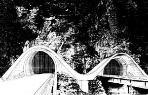
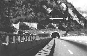
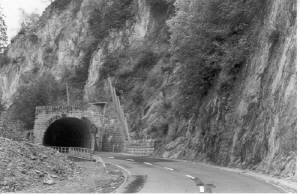
In the past a large number of portals were pro-tected against rock-fall through the use of artificial tunnels (that is to say a concrete structure protruding on the road), today it can be observed a large number of examples where net fences have been applied with good results in terms of safety and environmental impact (Fig. 1).
Recently a great deal of studies and new test procedures have been developed regarding net fences and on the basis of these results it is possible to define the key points for a correct design (Peila et al., 1998; Peila & Pelizza, 1998; Peila, 2000, Oggeri & Peila, 2000; Gerber & Haller, 1997). Since tunnel experts are not often aware of the design and technical improvement of these new tecnologies, which are mainly used in land protection, it seems appropriate to present and discuss these development and to give suggestions for a correct design.
2.The influence of geo-technical characteristics on tunnel portal design
Generally speaking, the main factors that influence tunnel portal design and construction techniques are:
- site morphology and topography;
- geological and geotechnical conditions in-cluding slope stability;
- surface water (rivers, irrigation canals, etc.) and groundwater;
- surface constraints (i.e. buildings, infras-tructures, etc.);
- environmental constraints: noise, landscape impact, etc.;
- safety aspects during operation and con-struction (for example risk of avalanches);
- alignment considerations and orientation (dazzling condition);
- work site location and construction times.
Among these factors, environmental constraints and rock mass geotechnical aspects are those which usually mainly influence the choice of the most suitable technical solution. Time factors should not be forgotten: the portal should be developed quickly so that the tunnel can be started to be dug as quick as possible.
The construction methods should in fact be divided by taking into account whether ground reinforcing techniques are necessary or not. When a rock mass is encountered (even though weak or with joints), it is possible to open slopes with high dips and important reinforcing works are not necessary. In this case is it possible to excavate a cut as far as the tunnel depth and then build the portal structures. If the slope is unstable or could be unstabilised by the excavation, it is necessary to take into consideration the possibility of building a provisional structure from which the tunnel excavation can be started. Many different tech-niques have been applied, such as conventional retaining walls, sheet pile walls (cantilevered or anchored), jet-grouting columns, steel pipes, conventional large diameter piles and conventional grouting ground reinforcing. When these conditions are present, the tunnel usually also has to be constructed using ground reinforcing techniques (Peila and Pelizza, 1993). It must be emphatized that only in the case of small rock elements the concrete liming of the postal can protect the road, in fact when the boulders are of great size the structure can have some stability problems during the impact, it is therefore necessary to build an embankement on the concrete structure able to dissipate the kinetic energy of the block.

The construction of a tunnel portal in a rock mass generally requires an excavation whose shape and dimensions are closely linked to the morphological conditions of the slope and this is usually obtained using explosives. In these cases many different solutions can be adopted for the final portal layout since the stability problems are generally reduced and the most important aspect is linked to architectural and environmental design. In these cases the main geotechnical problem is usually the collapse of rock blocks that are isolated by joints, with their subsequent movement towards the road and the tunnel portal. These problems can occur both during construction and while the tunnel is in use, with great risk for the traffic. In both cases, the problem requires the stabilising of the rock slope using active techniques that are able to prevent movement (bolts, tendons, nets in aderence on the slope, etc.) or intercepting the rock blocks before they can reach the road (or the railway) using passive techniques (net fences, ditches, walls or an artificial tunnel in concrete). In the first case the design should be carried out through the evaluation of the sta-bilization forces that are necessary to prevent the movement of the rock blocks. In the second case, the structures should be able to intercept the already moving boulder and stop it by adsorbing its kinetic energy (Fig. 2).
3. The characteristics of net fences
Net fences (Fig. 3) are structures that are able stop the movement of falling rock masses and can be divided into: limited deformability or elastic barriers and highly deformable barriers. Limited deformability barriers are structures that are designed to stop the block in movement with a reduced displacement of their elements (in a mainly elastic field). Deformable barriers are able to carry out plastic work with the setting up of permanent even large deformations to absorbe the kinetic energy (usually within the energy field between 200kJ and 5000kJ, that are equivalent to a block of 2m3 moving at a speed range of 10-30m/s)
Fig. 3 Example of high deformability net fences installed on a slope (courtesy SAFE Srl) |
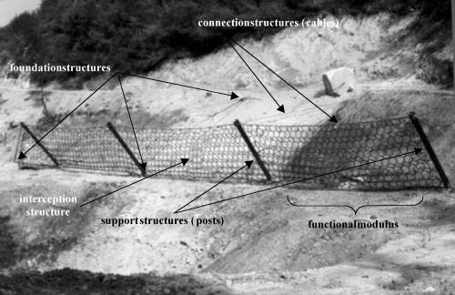
Fig. 4 Main elements of a net fence |
3.1 Functioning principles and general characteristics
A net fence should be able to intercept the trajectories of blocks in motion on a slopes within its interception surfaces and should be able to stop the block which means that the barriers can become deformed, without breaking, and carry out elastic and plastic work of an entity that is equal to the energy of the moving block. The main elements which make up a net fence are (Fig. 4):
a) interception structure, usually made up of steel cable nets, in a square, rhomboid or circular shaped mesh, with the function, of bearing the direct impact of the massand uniformly transmitting the stresses to the connecting structure, the support structure and the foundations;
b) support structure, usually made up of either open of closed steel pipes or beams (also named posts), with the function of ppreventing the interception structure which is by nature not rigit, form becoming unbent;
c) connection structure, usually made up of steel cables with the function of transmitting the stresses to the foundation structure. Devices that permit a controlled lengthening can be installed on the structure to allow deformation.
d) a foundation structure which is usually made up of cable, bolts or concrete plinths (often anchored to the ground with bolts), with the function of transmitting the forces derived from the impact to the ground.
The used materials are steels, aluminium aloys, composed materials or others which depend on the producer or the designer. Since this structure must maintain its effectiveness in time in the open air and often in a mountain side area (where the climatic conditions are extreme) the constructor should therefore use materials which are not influenced by the exposition to the sun, humidity, cold and alternation of freezing and melting. The nets are made up of metallic cables of different types: they can be made of steel cables linked together by clamps to make square or romboidal shapeD or submarine ring nets. The maximum surface of the void left by the main mesh is not usually more than 1400cm2 and a mesh with a finer meshwork can be placed on top in order to stop smaller stone elements.
Net and posts are connected to the foundations through metallic cables which constitute the main structural part of the barrier and should be dimensioned according to the loads tranferred by the block to the barrier during the impact.
The foundations are designed and constructed to resist the foreseen forces both in the static and dynamic fields. It is therefore necessary to correctly define the forces that act during impact.
The elements that transmit the stresses to the ground should in particular be adequateto the characteristics of the ground, and dimensioned on the basis of a specific project even though very few tests have so far been carried out to verify the dinamic behaviour of foundations (Muraishi and Sano, 1999). In practice the use of the usual statical design is normally applied.
Often energy dissipator devices are installed on the cables. These are elements that are able to balance the forces which act on the structure and transform part of the block energy into plastic work. Many different structures can be found on the market with different energy dissipation concepts.
4. The behaviour of a net fence during impact
During impact a net fence is solicited and deformed by the falling block and the stopping forces are transmitted to the foundations (Fig. 2).
For this reason the design of these structures should be based on the results of full scale tests (Peila et al., 1998). These tests are normally carried out by dropping natural stone blocks or artificially prepared concrete blocks, allowing them to reach a certain speed so that they hit the structure at a minimum speed of 25m/s. At the moment of impact, the block should be completely free and unconnected to the means used for its mobilization and during the test no direct interference with the ground should occur until the block stops. Usign this tets it is possible to define the energy that a barried can adsorb for a standard impact.
During the test it is possible to measure the forces that act on the main foundations (upstream, downstream and lateral) and only with these data is it possible to develop a correct geo-technical project. These forces can, in fact, reach very high values, for example for a barrier designed for 1500kJ, the forces acting on foundations can reach 20t and be applied for a time of 0.5-1s.
The complete identification of a barrier that can be used for a correct design, should therefore include the following data :
- the energy which can be absorbed in safe conditions (overload energy);
- the usefull height (i.e. the height at which the barrier is able to absorb the overload energy);
- a detailed description of the barrier, with technical specifications of the used materials;
- assembly instructions, with tollerences of installation on the site;
- the maximum displacement during impact;
- full scale test results;
- the values and direction of forces acting on the foundations during the impact.
Fig. 5 Schematic section of the test site used for full scale tests on net fences (Peila, 1999)
5.An example of net fence positioning
With specific reference to net fence design the following steps should always be considered:
- a detailed topographical, geological and geomorphological survey of the area followed by a geotechnical study in order to define the physical-mechanical characteristics of the rock mass of the slope
- the ground and the rocks, including the discontinuities and the entity of water pressure,
- the definition of possible detachement points, the foreseeable block size
- the most probable trajectories (through back- analysis on the basis of historical information of previous collapses);
- the probability of interception of the blocks on the basis of the positioning of the barriers using forecast calculation (usually carried out using a probabilistic approach);
- the energy that should be dissipated during the impact and therefore the choice of the barrier with reference to the energy level product to be used.
Furthermore as part of the design documents, the following should always be taken into account:
- the drawings of the net fences (including the position of the foundations) and the objectives to protect;
- a technical description of the net fence;
- a calculation document that completely describes the devices used to transmit the stresses to the ground (anchorages) ; the hypothesis considered in the calculation and the applied safety coefficient. This document should indicate the dimensional characteristics of the foundation elements precisely;
- a document that report the durability conditions of the barrier, the maintenance procedure and the relative hygiene and safety rules ;
- the hygiene and safety measures (in com-pliance with current regulations) that shpould be adopted during the works.
An example of a bidimentional simulation of rock fall from an artificial rock slope and the best positioning of a net fence is here presented. The adopted section (bidimentional) is described by the following coordinates:
After the definition of the size and weigth of the block that will be used as the basis for the design (in this example with a diameter of 1.2m and mass of 21kN), it is necessary to define the geotechnical parameters of the model (in a lumped mass model the Restitution Coefficients are the key parameters) (Giani, 1992; Mandrone & Peila, 1995; Peila, 2000) and to carry out the symulation of the possibile trajectories with and without the net fence.
Some of the computed trajectories are shown in figs 6 and 7 are. The percentage of block intercepted by the net fence evaluated on the basis of 5000 simulations are summarized in table 3.
From the simulation it is possible to show that it is possible to reduce the percentage of blocks intercepting the area near the portal to 1% with a 4m high barrier able to dissipate an energy of 1800kJ.
6. Conclusions
Portal design requires a multi-disciplinary approach that should involve alignment designers, geologists, geotechnical and civil engineers, architects and environmentalists since the final target is to guarantee the environmental impact while fulfilling all the structural and safety requirements (Pelizza et al., 1998).
In rock slopes, portals are often subjected to the risk of rock fall. In this case it is possible to protrude the portal to create an artificial tunnel of a sufficient length to protect the road. The design of these structures can be difficult since, if the energies involved are high, it is necessary to cover the concrete arch with granular soil or the kinetic energy of the falling block will make the rigid structure collapse. As an alternative to this solution, it is possible, (and had been frequently used), to install net fences on the slope which have have proven to be very efficient in the protection of roads and railways but which require specific and detailed design. Furthermore, from the most recent developements in the sector it would appear that the sytematic use of full scale tests is necessary for a correct choice of the various products on the market and therefore for the final design.
