

1. Introduction
2. Safe Tunneling Method
3. Development of Stability Analysis Program Using Key Block Theory
1) Input data of tunnel shape
2) Discontinuity data input
3) Detection of unstable blocks
4) Stability analysis
5) Design of additional support
4. Application to the Long Tunnel
4.1 Input information and investigation of strength of discontinuity
4.2Flow of the application to the long tunnel
4.3 Detection of key blocks
4.4 Supplementary support of key blocks
5. Verification of the Effectiveness of Supplementary Support
6. Conclusions
1. Introduction
Since about 70 percent of the territory is mount-ainous, more tunnels are constructed in Korea for maximizing the development efficiency. With the increasing number of tunnel construction, safe and quick construction in tunnels has been emerged as the utmost important subject (Hwang, 2003; Hwang et al., 2004). Recently, the number of long tunnel construction is steeply increased because of the request for high speed and straight road. A large sectional tunnelling method using TBM is expected to be popular as domestic demand of long tunnel gets growing.
The properties of rock masses are important factors relevant to the construction of tunnels (Ohnishi, 1999; Hwang and Sato, 2004). In discontinuous rock masses, rock blocks which have a variety of shaped and sizes are formed geometrically along discontinuities (Ohnishi, 2002; Hwang et al., 2003c). When the rock mass is excavated, the new shape of block appears on the excavated surface. The block theory was suggested by Goodman and Shi (1985). The thrust of the block theory is to produce techniques to specify the critical discontinuity blocks intersecting excavation. Excavations in discontinuous rock masses are frequently affected by key blocks (Ohnishi et al., 1985). The key block analysis is extremely helpful in studying the design of excavation and support requirements.
This paper describes the safe tunneling method and development of a computer simulation method with user-friendly interfaces to apply the key block analysis on actual sites to investigate the stability of tunnels based on the behaviors of discontinuous rock masses and to design supplementary supports when detected blocks are unstable. A safe tunneling method using numerical modeling of rock blocks is proposed, then applied to the long tunnel based on real discontinuity information observed in situ.
2. Safe Tunneling Method
Knowledge of the properties of rock masses is needed to predict the stability of the tunnel during construction. Especially poor geological sections, such as fractured zones of faults, have adverse effects on the progress of the works and may need construction methods and support patterns to be changed. Such poor geological sections should be detected and the properties of the rock masses should be understood prior to the excavation. The safe tunneling method using numerical modeling of rock blocks actively utilizes various kinds of information. It also helps engineers to make decisions concerning measurements, analyses and designing, construction, and optimization of designing and construction.
The procedure of this safe tunneling method with TBM is shown in Fig. 1. First, the TBM tunnel is excavated. During the excavation of the TBM tunnel, an investigation was performed, and dis-continuity information was acquired. Before the excavation of the main tunnel, support pattern for the large section is designed based on the actual TBM excavation results. At the same time, dis-continuity information from TBM tunnel wall was collected and unstable blocks of the main tunnel were detected by the key block analysis. When unstable blocks of the main tunnel were detected, additional reinforcement was applied before main tunnel excavation. The reinforcement from TBM tunnel made construction more safely and brought the cost saving and construction lead time in terms of preventive action for unexpected collapse.
3.Development of Stability Analysis Program Using Key Block Theory
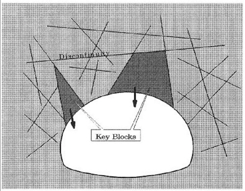
When the rock mass is excavated, the new shape of block appears on the excavated surface. As for the assessment of the rock structure induced failures, the so-called block theory was suggested by Goodman and Shi (1985). The thrust of the block theory is to provide a technique to specify the critical discontinuity blocks intersecting an excavation. The block theory is concerned with the three-dimensional configuration of rock blocks as determined by the discontinuity geometry, and how the removability and stability of these blocks are affected by excavation. Fig. 2 shows key blocks around a tunnel. The key block analysis is very helpful in studying the design of excavation and support requirements.
It is possible to detect key blocks all along the tunnel exactly by using the developed Key Block Analysis Program for the safe tunneling method in the long tunnel. This computer simulation method with user-friendly interfaces can calculate not only the stability of key blocks but also the design of supplementary supports if necessary. The computer simulation method with user friendly interfaces can apply the key block analysis on site to investigate the stability of tunnels based on the behaviors of discontinuous rock masses and to design supplementary supports when detected blocks are unstable.

The items examined in developing a numerical analysis program for the safe tunneling method are shown in the following.
①It can cope with an optional cross section and alignment of tunnel to make it have a generality.
②The shapes and locations of key blocks are detected precisely based on the geometrical information of discontinuities, which are absolute three dimensional coordinates, strike, dip, alignment for tunnel and so on.
③The result of key block analysis can be acquired in a short time for the daily management.
④It is possible to eliminate and/or revise the data of discontinuities easily.
The program has been developed considering the above-mentioned items. The contents of the developed key block analytic procedure were described in the following.
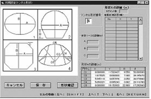
1) Input data of tunnel shape
The plan view and a cross-section view of a tunnel are inputted. An example of the cross- sectional view of the tunnel inputted the program is in Fig. 3.
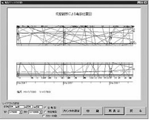
2) Discontinuity data input
A position, strike, dip etc. are inputted (Fig. 4).
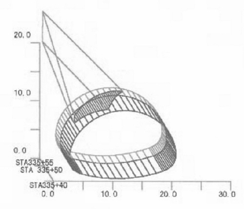
3) Detection of unstable blocks
Unstable blocks are detected (Fig. 5).
4) Stability analysis
A stable evaluation for reinforcement execution of unstable blocks is performed.
5) Design of additional support
The most suitable position, number and length of rock bolts are calculated to anchor the rock mass outside of the key blocks and to maintain the stability (Fig. 6).
4. Application to the Long Tunnel
The actual application site selected in this study is the long tunnel under construction. The safe tunneling method using numerical modeling of rock blocks is applied to the long tunnel with a large cross section of about 200 m2. The long tunnel is under construction examining standard support system for large rock tunnel. Moreover, the tunnel has a possibility for rock masses to fall of slide along discontinuities not only because the rock mass have a lot of discontinuities but also because the cross-section of the tunnel is very large and flat. Therefore, a key block analysis was introduced based on the behaviors of discontinuous rock mass during the construction of a tunnel as well as after opening it to the public. This tunnel construction is the world's first long tunnel construction based on block theory.
The cross section of the tunnel is big and flat. The long tunnel is 3,800 m long. Fig. 7 shows the standard cross-section of the tunnel. The standard cross-section of the tunnel is very large (200 m2) and wide (18 m) compared to ordinary tunnels. The final tunnel shape is flat with a height to width ratio of 0.65. The very large cross section tunnel is under construction. The 5 m diameter Tunnel Boring Machine (TBM) pilot tunnel is at the center in the proposed tunnel. After the TBM pilot tunnel was excavated, the main tunnel is enlarged by New Austrian Tunneling Method (NATM).
The TBM Pilot and Enlargement Excavation Method, in which a pilot heading is excavated efficiently in advance utilizing the TBM capability for high speed excavation, is expected to provide various beneficial effects including drainage into the pilot and stability of the face. First, a working tunnel, which was 300 m long, was excavated about 1km to the west from the east portal because of the topographical condition and the temporary storage yard of muck waste. Secondarily, a pilot tunnel by TBM was excavated to the west. Finally, a pilot tunnel is under enlargement by NATM.
4.1 Input information and investigation of strength of discontinuity
Before applying a key block analysis to the site, the input information should be provided to the program such as absolute three dimensional coordinates, strike and dip of discontinuities, strength of disc-ontinuities (cohesion C and friction angle φ), unit volume weight.
Discontinuity orientations in three-dimensional space are represented by two parameters, the strike and dip of the line of steepest declination in the plane of the discontinuity. The mutual orientation of discontinuities will determine the shape of the individual blocks, beds or mosaics comprising the rock mass. Discontinuity orientation is described primarily by the relationship between the orientations of all discontinuities within a rock mass.
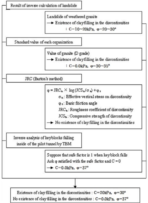
Among them, strength of discontinuities analysis, same values of strength of discontinuities were used regardless of conditions of discontinuities. However, the strength of discontinuities is depending upon the existence of clay in the discontinuities. Therefore, two cases for the existence of clay in the disco-ntinuities were examined. Fig. 8 shows the Invest-igation of strength of discontinuity. As a result of the examination shown in Fig. 8, cohesion C is 20 kPa and the friction angle φ is 30o in the case of existence of clay filling. On the other hand, cohesion C is 0.0 kPa and an friction angle φ is 37o in the case of no existence of clay filling. Further, the strength of discontinuities to get more accurate C and φ by simple shear test was re-examined.
4.2Flow of the application to the long tunnel
In the excavation of the long tunnel, a pilot tunnel by TBM is followed by enlargement by drill and blast in NATM. Key block analysis can be divided into two stages. The first stage is after completion of the pilot tunnel (D=5 m) and the second stage is under construction by NATM. At the first stage, based on the information of rock discontinuities acquired during the excavation of the pilot tunnel, detected key blocks are supported before enlargement by NATM. At the second stage, based on the observation of the excavated surface after enlargement, in addition to the information of rock discontinuities which were not observed at the first stage, key block analysis is applied again. Furthermore, the stability of key blocks detected at the first stage is re- examined and supplementary supports are installed in case of unsafe ground condition.
4.3 Detection of key blocks
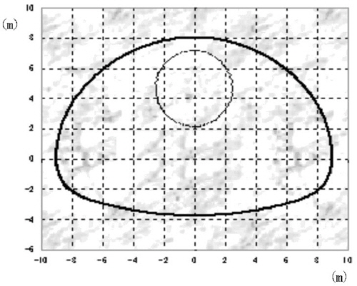
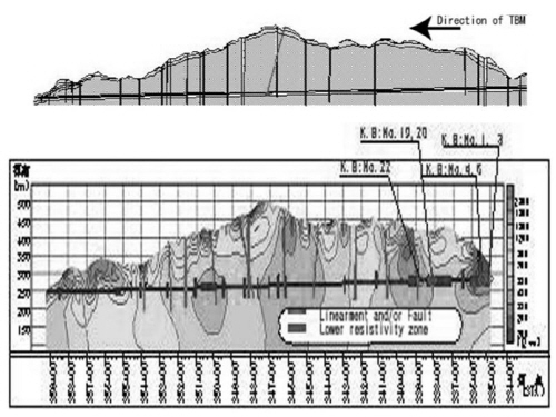
At the first stage, 38 key blocks were detected in total all along the tunnel. According to the above-mentioned method, seven key blocks were judged to be very unstable because they could not be supported by standard supports. Fig. 9 shows positions of these seven key blocks. Almost all of these seven key blocks have a slender wedge shape in the up-down direction because vertical rock discontinuities are dominant in the site.
4.4 Supplementary support of key blocks
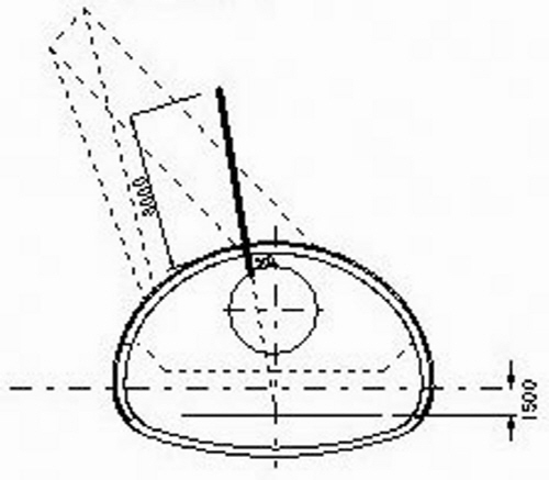
Supplementary supports were installed to these seven key blocks from inside of the pilot tunnel before enlargement by NATM. An example of supplementary supports of key block No.4 is shown in Fig. 10. As for the material of support, we used skin friction type of rock bolts, i.e. Connectable Swellex, because they had large resistance for shearing along rock discontinuities and adhesive strength to rock mass was strong in comparison with ordinary rock bolts. In addition, the most suitable position, number and length of rock bolts were calculated in this method to anchor the key blocks to the rock mass and to maintain the stability.
5. Verification of the Effectiveness of Supplementary Support
One rock discontinuity of key block No.19, which was judged to be unstable, was measured. A three- dimensional joint displacement measuring instrument was installed crossing the detected rock discontinuity from inside of a pilot tunnel before enlargement by NATM directly below key block No.19. Behaviors of the rock discontinuity were measured and analyzed every thirty minutes automatically until the face passed through it.

The effectiveness of supplementary support to key block was verified by the falling of a rock block under enlargement below key block No.3. A rock block of 5m in height fell along a rock discontinuity of the key block. The rock block above the tunnel was supported and fixed by skin friction type of rock bolts. According to the safe tunneling method using numerical modeling of rock blocks, supplementary supports were installed to these seven key blocks from inside of the pilot tunnel before enlargement by NATM(Table 1).

6. Conclusions
This study has proposed the safe tunneling method using numerical modeling of rock blocks in long tunnels. Then the application of the safe tunneling method using numerical modeling of rock blocks to the long tunnel with a large cross- section is described. The long tunnel is the first site that this method was applied based on actual rock discontinuity information observed in the field. The long tunnel is under enlargement by NATM applying key block analysis. A user-friendly stability analysis software was developed and its application was introduced. It was possible to exactly detect key blocks on tunnel surface by using the numerical analysis program developed for the safe tunneling method using numerical modeling of rock blocks in long tunnels. At the long tunnel, seven key blocks which could not supported by standard support were detected. Supplementary supports were installed to these seven key blocks before enlargement by NATM. The effectiveness of the proposed safe tunneling method using numerical modeling of rock blocks has been verified by the confirmation of the predicted key block during the enlargement excavation.
