

1.Introduction
2. Bangkok MRT Subway
2.1 Bangkok Subsoil Conditions
2.2 Subway Construction Technique
2.3 Soil Deformation Response due to Bored Tunnelling
2.4 Prediction of Ground Displacement Response
3. Flood Division Tunnel
3.1 Tunnel Alignment and Subsoil Conditions
3.2 Damage Assessment before Tunnel Bored through Obstruction
3.3 Ground Displacement Caused by Tunnel Bored underneath Obstructions
4. Conclusions
1.Introduction
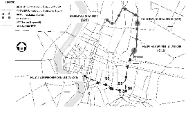
This paper presents two case studies for tunn-elling in Bangkok : a subway tunnel site and a flood diversion tunnel site. The first case study is related to ground displacement response for dual tunnel Bangkok MRT subway. Construction of the first blue line subway 20 km long, the Metro-politan Rapid Transit Authority (MRTA) project has been started since 1996. The project consists of 18 underground stations running from the central main state railway station called the Hualamphong Station (S1) and goes through the business area, passes the bus terminal and ended at the Bangsue Station (S2) as shown in Fig. 1 This first subway was completed and opened in August 2004. The next phase of the MRT subway is extended from this year 2005. The behavior of ground surface settlement during tunnelling is presented based on instrumented record at various stages and time of construction. Back- analyses of ground surface response by means of FEM analysis are also presented.
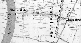
Meanwhile, the second case study is related to the EPB tunnelling bored underneath through underground obstruction. In rainy season, flood--ing in Bangkok city is one of the crises to the city which is responsible by the Bangkok Metro-politan Authority (BMA). The first flood diver-sion tunnel so called Klong Premprachakorn flood diversion tunnel was constructed to divert the flood water in the area North area of Bangkok city to Choapraya river as shown in Fig. 10 This first shortcut tunnel was about 1.88 km long. Along the route, the tunnel was bored underneath through two underground obstructions as the existing Bangkok main water supply tunnel and the bridge crossing the cannel. During flood diversion tunnel bored underneath the existing Bangkok main water supply tunnel and pile fou-ndation of the bridge, instrumentation was moni-tored and compared with predicted FEM analysis. The prevention risk potential by means of pred-icting damage assessment is also presented and discussed.
2. Bangkok MRT Subway
2.1 Bangkok Subsoil Conditions
The project consists of 18 underground stations running from the central main state railway station called the Hualamphong Station (S1) and goes through the business area, passes the bus terminal and ended at the Bangsue Station (S2) as shown in Fig. 1 Subsoil investigations were initially carried out during feasibility study. The post-tender site investigations were carried out during construction in order to confirm the subsoil conditions, to determine the existing piezome-tric levels, and to determine the design soil para-meters. Over 200 boreholes as well as six numbers of self-boring pressuremeter tests were carried out. The general subsoil conditions are presented in Fig. 3.
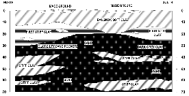
The subsoil consists of 13-16 m thick soft marine clay. This clay is sensitive, anisotropic and creep (time dependent stress-strain-strength behavior) susceptible. These characteristics have made the design and construction of deep base-ments, filled embankments and tunneling in soft clay difficult. The first stiff to very stiff silty clay layer is encountered below soft clay and medium clay varying from 21 to 28 m depth. This first stiff silty clay having low sensitivity and high stiffness is appropriate to be the bearing layer for the subway tunnels. The groundwater condition is hydrostatic starting from 1.0 m below ground level. Deep well pumping from the deep aquifers has led to the under drainage of the soft clay and stiff clay as well as deeper soil layer. The piezometric level or the phreatic sur-face of the Bangkok aquifer is, therefore, redu-ced and quite constant at about 23 m below gro-und surface as shown in Fig. 4. The subway tunne-ling was designed to be seated mainly in the first stiff silty clay layer between 15-22 m in depth below ground surface which having very high stiffness and expecting very low or minor gro-und loss during TBM boring.

2.2 Subway Construction Technique
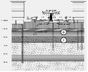
The subway construction technique was firstly started with only a small launching shaft at one end of the station, then followed by tunneling works and concurrently subway station constr-uction by top down construction technique. The instrumentation related to monitoring the soil displacement during tunneling consists of the surface settlement points, extensometer, inclino-meter and convergent bolts. The tunnel was desi-gned as a reinforce concrete segmental lining of about 0.3 m thick with outside and inside diameter of 6.3 m, and 5.7 m, respectively. The Earth Pres-sure Balance (EPB) shield technique was used to bore the tunnel. Generally, dual tunnels in parallel arrangement with spacing between tunnel of about 15 m is designed as shown in Fig. 5. How-ever, between station S1 (Hua Lumpong) to S6 (Sirikit) due to the obstruction of the existing main Bangkok water supply tunnel (MWA Tunnel) of about 3.5 m in diameter, the dual tunnels were arranged in vertical stack direction as shown in Fig. 6.

2.3 Soil Deformation Response due to Bored Tunnelling
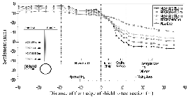
The ground surface displacement response during bored tunnelling was monitored by means of geot-echnical instrumentation. The ground surface and subsurface response due to shield tunnelling can be classified according to position of TBM passing through the measured point into 3 stages as the deformation ahead the shield, deformation at the shield, and deformation behind the shield. This deformation behavior recorded between stations Bonkai (S5) to Sirikit (S6) is presented in Fig. 7. The deformation ahead the shield is mainly due to soil flow into the shield, while deformation behind the shield is due to effect of tail void and setting time. It is clearly showed that the displace-ment behind the shield is the major displace-ment both surface and subsurface due to tail void phenomena.
2.4 Prediction of Ground Displacement Response
The numerical approach to predict ground dis-placement response was performed based on FEM analysis. The two dimensional FEM namely PLA-XIS (Teparaksa, 2002) is used for modeling of the interaction between soil and structure. With this approach, a complete modeling of the system including the stress-strain distribution and gro-und water condition, the deformation and section force in the lining was also possible.
2.4.1 Soil Modeling
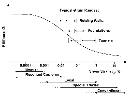
The constitutive model was based on an elasto- plastic (Mohr-Columb) failure criteria. As the recorded ground displacement response, it was occurred in the short term conditions, therefore, undrain soil parameters were assumed for the cohesive soil layers. The effect of ground water flow as well as consolidation was not considered in the model. The standard ground model used for the FEM analysis was based on the soil stif-fness parameters. Generally the stiffness of the Bangkok subsoils has the non-linear behavior depended on the shear strain level (Teparaksa 1999; 2000). For practical point of view, the plain strain concept with the Mohr-Coloumb soil model was used in the FEM analysis. Mair (1993) proposed the soil stiffness depending on the order of the shear strain as shown in Fig. 8. The range of shear strain for bored tunnel was recom-mended in the range of 0.1-1.0%. Six number of self boring pressuremeter tests were carried out along the MRT route. Teparaksa (1999) reported the results of the self-boring pressuremeter tests in Bangkok subsoil that the soil stiffness depen-ded on the degree of shear strain. According to the shear modulus from pressuremeter test and the order of shear strain for tunnelling works recom-mended by Mair (1993) between 0.1-1 %, the soil stiffness was assumed for FEM analysis as Eu/Su = 240 and 480 for soft clay and stiff clay, resp-ectively. The strength and definition soil para-meters are summarized in Table 1. Soil proper-ties for Mohr-Columb analysis are pre-sented in Table 2.
2.4.2 FEM Analysis
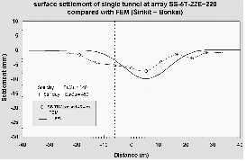
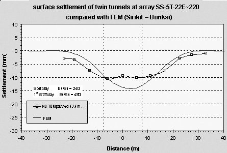
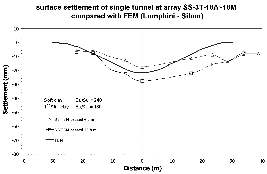
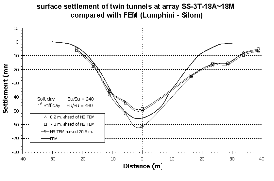
Fig. 9 shows the comparison between FEM predi-ctions of ground surface deformation response with the field performance for case of parallel dual tunnel between stations Sirikit (S6) - Bonkai (S5). Fig. 10 presents the comparison between FEM predictions of ground surface deformation response with the field measurement for case of vertical stack dual tunnel between Lumpini (S3) to Silom (S4) station. It can be seen that the FEM prediction of ground surface deformation response agrees well with the field performance. The range of shear strain between 0.1-1 % as recommended by Mair (1993) and Menzies (1997) as well as the soil stiffness in terms of modulus tested by means of self boring pressuremeter tests, therefore, can be used as combination with Mohr-Columb constitutive soil modelling to predict ground response due to bored tunnel.
|
(a) Single tunnel |
|
(b) Twin tunnels |
Fig. 9 FEM prediction of ground surface displace-ment for single and twin tunnels. |
3. Flood Division Tunnel
3.1 Tunnel Alignment and Subsoil
Conditions
The Premprachakorn flood diversion tunnel was the first diversion tunnel shortcut the floo-ding water from Premprachakorn cannel to Choa-praya river (Fig. 2). The tunnel has outside dia-meter of 4.05 m with reinforced concrete segm-ental lining of 180 mm thick and bored by means of EPB shield. The tunnel was seated in the very stiff silty clay layer alternated with dense silty sand layer at about 20-24 m below ground surface as shown in Fig. 11. At station 1+534 from Cho-apraya river, the flood diversion tunnel was bored about 3 m underneath through the existing Bangkok main water supply tunnel as shown in Fig. 12. Generally the TBM was bored based on the face pressure of about 100-120 kN/m2 which is about 45-55 % of the at rest earth pressure, however at portion where the tunnel have to pass underneath the existing main water supply tunnel, the face pressure was applied up to about 380 kN/m2 in order to minimize the ground loss as well as soil displacement. This technique could overcome the obstruction, however, polymer lubri-cant had to be added to solve the slip of stiff clay in the cutting process. After just 18 m through this water supply tunnel, at station 1+552 and 1+573 the diversion tunnel was also bored about 0.5-1.5 m below pile foundation of the main bridge across to the raw water cannel as shown in Fig. 13. This bridge is quite old and its as- built drawing is not available. Therefore, the side echo integrity tests were carried out under water to determine the pile length. Therefore, the exact pile length was not clear. At the area of this tunnel bored through the substructure obstruction, the detail instrumentation were installed at 3 sections as station 1+502, 1+512 and 1+522 and monitored. Grouting technique around the tunnel was used to support the pile foundation.
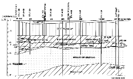


The general subsoil conditions of Bangkok sub-soils consists of 13-15 m thick soft marine clay underneath by stiff to very stiff silty clay layer to about 22-24 m depth. This soft clay is the sensitive clay having anisotropic behavior with water contents about 85-95 % with undrained shear strength about 15.5-16 kN/m2. The first dense silty sand layer is found beneath the very stiff silty clay layer to about 30-35 m depth and alternated by hard silty clay and second very dense silty sand layer. The piezometric draw down water level is found at about 23 m depth below ground surface due to deep well pumping and lead to induced land subsidence in Bangkok city.
3.2 Damage Assessment before Tunnel Bored through Obstruction
In order to prevent the risk potential on both Bangkok main water supply tunnel and pile fou-ndation of the bridge across the raw water cannel, the damage assessment by means of FEM analysis was carried out. Two tested sections at station 0+506 and 0+980 were fixed with fully installation of instrumentation to verify the ground displace-ment response (Ground surface settlement point and extensometer).
3.2.1 Ground Modeling
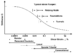
The constitutive model was based on an elasto- plastic (Mohr-Coulomb) failure criteria. As the recorded ground displacement response, it was occurred in the short term conditions, therefore undrained soil parameters were assumed for the cohesive soil layers. The effect of ground water flow as well as consolidation was not considered in the model. The standard ground model used for the FEM analysis was based on the soil stif-fness parameters. Generally the stiffness of the Bangkok subsoils has the non-linear behavior depending on the shear strain level. For prac-tical point of view, the plain strain concept with the Mohr-Coulomb soil model was used in the FEM analysis. Menzies (1997) proposed the soil stiffness depending on the order of the shear strain as shown in Fig. 14. The range of shear strain for bored tunnel was recommended in the range of 0.1-1.0%. Six self boring pressure-meter tests were carried out along the MRT route. Teparaksa (1999) reported the results of the self-boring pressuremeter tests in Bangkok subsoil that the soil stiffness was depended on the degree of shear strain. According to the shear modulus from pressuremeter test and the order of shear strain for tunnelling works recom-mended by Menzies (1997) between 0.1-1 %, the soil stiffness was assumed for FEM analysis as Eu/Su = 240 and 480 for soft clay and stiff clay, respectively. The strength and stiffness soil para-meters are summarized in Table 1.
3.2.2 Damage Assessment
The damage assessment is carried out to predict the ground surface and subsurface response caused by EPB shield tunnelling. Fig. 15 presents the predicted ground surface and subsurface response by means of FEM analysis compared to field measurements at station 0+980. The predi-ction agrees well with field performance.
3.3 Ground Displacement Caused by Tunnel Bored underneath Obstructions

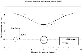

At station 1+522 where is about 10 m before crossing the MWA water tunnel, the predicted displacement of MWA water tunnel was about 19 mm at about 15 m below ground surface. Fig. 16 presents the FEM predicted ground displacement compared with field measurement by surface settlement point and deep rod extensometer. At the station where the Premprachakorn flood diver-sion tunnel passed underneath the MWA water tunnel (station 1+534) and pile foundation of the bridge (station 1+573), only ground surface displacements was monitored. In the area of prot-ection zone of MWA tunnel, any drilling or boring even for deep instrumentation was not allowed.
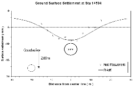
Fig. 17 and Fig. 18 present the ground surface response predicted by means of FEM analysis com-pared with field measurement at station 1+534 (crossing the MWA tunnel) and station 1+573 (crossing the bridge foundation), respectively. The FEM prediction agreed well with field performance.
4. Conclusions
Two case studies for tunnelling in Bangkok city are reviewed in this paper: a subway tunnel site and a flood diversion tunnel site. The first case study was related to ground displacement response for dual tunnel Bangkok MRT subway. The ground surface settlement was monitored during and after completion of the MRT subway tunnelling. The deformation ahead the shield was mainly due to soil flow into the shield, while deformation behind the shield was due to effect of tail void and setting time. It is clearly showed that the displacement behind the shield is the major displacement both surface and subsurface due to tail void phenomena. Considering inter-action between soil and structure in numerical modeling renders a complete modeling of the system including the stress-strain distribution and ground water condition, the deformation and section force in the lining. The prediction of ground surface response due to shield tunneling by FEM analysis agreed with field performance. Meanwhile, the second case study was related to the EPB tunnelling bored underneath through underground obstruction. The flood diversion tunnel was bored underneath two underground obstructions as existing main Bangkok water supply tunnel, and the bridge pile foundation crossing the raw water cannel. The damage assessment by means of FEM analysis to verify the risk potential was carried out and compared with measurements before reaching the obstru-ction. The behavior of ground surface and subsur-face response during and after passing the obstruction was also presented. The FEM predi-ction agreed well with field performance. Some lessons experienced through case studies will be helpful for tunnelling in soft soils in Korea.